High-definition video signal transmission method and device
A high-definition video and signal transmission technology, applied in the field of communication, can solve the problem of video quality and real-time performance being difficult to guarantee, and achieve the effect of ensuring video quality and real-time performance.
- Summary
- Abstract
- Description
- Claims
- Application Information
AI Technical Summary
Problems solved by technology
Method used
Image
Examples
Embodiment 1
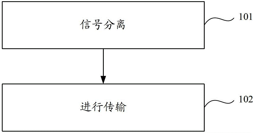
[0023] Embodiment 1 of the present invention provides a high-definition video signal transmission method, the steps of the method can be as follows figure 1 shown, including:
[0024] Step 101, signal separation.
[0025] In this embodiment, the luminance signal and the chrominance signal in the high-definition video signal need to be transmitted separately. Therefore, in this step, the high-definition video signal needs to be processed, and the luminance signal and the chrominance signal are separated from the high-definition video signal, so that subsequent operations can be performed on the separated luminance signal and chrominance signal.
[0026] Step 102, perform transmission.
[0027] In this embodiment, an analog signal transmission method is used to transmit high-definition video signals. Therefore, in this step, the luminance signal and the chrominance signal may be transmitted in an analog signal transmission manner. In order to ensure that the luminance signal...
Embodiment 2
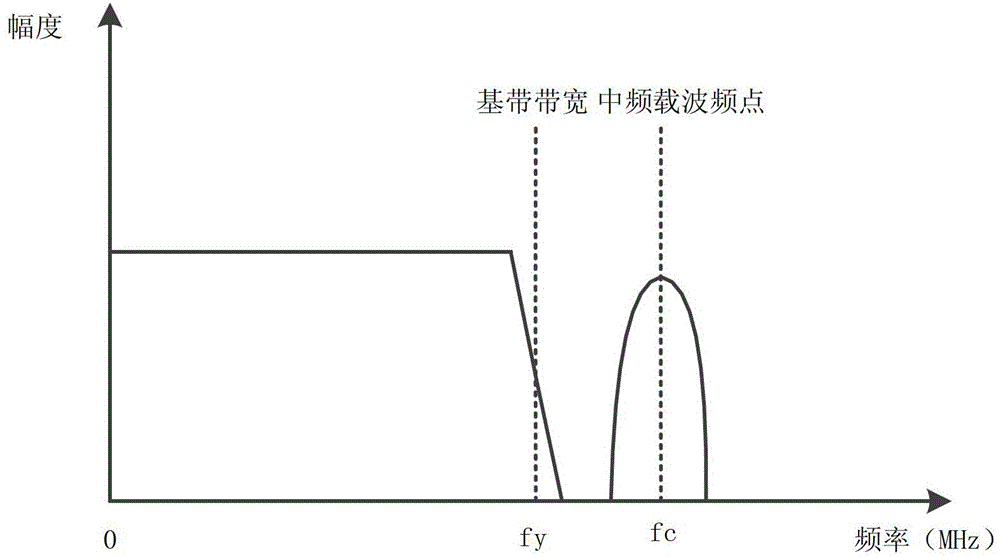
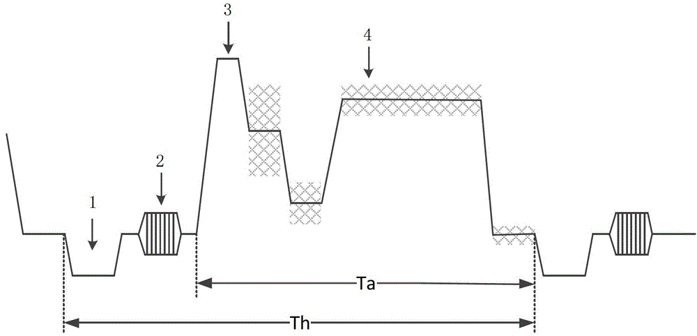
[0035] Such as figure 2 Shown is the analog signal frequency domain diagram of 720P high-definition video signal, including: the analog signal is divided into signal bandwidth, in order to meet the requirements of long-distance transmission, according to the standard of coaxial cable signal attenuation, determine the upper limit of all signal bandwidth as fmax, Generally fmax adopts 20MHz. According to the frame rate and horizontal resolution requirements, the bandwidth of the luminance signal is determined to be fyMHz, generally 15MHz. According to the color resolution requirements of high-definition video signals, the bandwidth of the chrominance signal is determined to be fcd, generally 4MHz, and further according to the set frequency gap, the carrier frequency point of the chrominance signal is determined to be fcMHz, and the set frequency gap is generally 1MHz, that is, generally 18MHz is used as the carrier frequency point. In addition, the frequency bands occupied by...
Embodiment 3
[0039] Embodiment 3 of the present invention provides a high-definition video signal transmission device, the structure of which can be as follows Figure 4 shown, including:
[0040] The separation module 11 is used to separate the luminance signal and the chrominance signal from the high-definition video signal; the transmission module 12 is used to transmit the luminance signal and the chrominance signal by means of analog signal transmission, wherein the luminance signal and the chrominance signal The frequency bands occupied by chrominance signals during transmission do not overlap.
[0041] The transmission module 12 is specifically used to convert the luminance signal into a luminance quantized value, modulate the chrominance signal and load it onto an intermediate frequency carrier to form a quantized value after the chrominance signal modulates the carrier, and modulate the luminance quantized value and the chrominance signal The quantized values after the carrier ...
PUM
 Abstract
Description
Claims
Application Information
 - R&D
- Intellectual Property
- Life Sciences
- Materials
- Tech Scout
- Unparalleled Data Quality
- Higher Quality Content
- 60% Fewer Hallucinations
Browse by: Latest US Patents, China's latest patents, Technical Efficacy Thesaurus, Application Domain, Technology Topic, Popular Technical Reports.
© 2025 PatSnap. All rights reserved.Legal|Privacy policy|Modern Slavery Act Transparency Statement|Sitemap|About US| Contact US: help@patsnap.com


