Photovoltaic junction box

A technology of volt junction box and terminal, applied in the field of solar photovoltaic modules, can solve the problems of large size of the junction box, decreased waterproof performance, troublesome production process, etc., and achieve the effects of large contact area, short production time, and simple and convenient production process

Inactive Publication Date: 2012-10-10
CHANGSHU FRIENDS CONNECTOR TECH
View PDF3 Cites 1 Cited by
  • Summary
  • Abstract
  • Description
  • Claims
  • Application Information

AI Technical Summary

Problems solved by technology

[0002] The junction boxes currently on the market generally use a shell with an open back. There are electrical terminals in the shell to electrically connect the busbars at the output end of the solar cell template power with the input ends of the corresponding electrical terminals. The cables pass through one side of the shell. The holes extend into the housing and are electrically connected to the output hole on the other side of the electrical terminal. However, due to the existence of the electrical terminal, the junction box has a large volume and poor heat dissipation. The cable hole on the housing will cause the waterproof performance of the product. decline
For this reason, the sealed junction box made by filling glue uses the heat conduction, insulation and resistance of silica gel to meet the needs of the junction box, but this method is troublesome to make and takes a long time to cure.

Method used


Image

  • Photovoltaic junction box
  • Photovoltaic junction box
  • Photovoltaic junction box

Examples


Embodiment 1

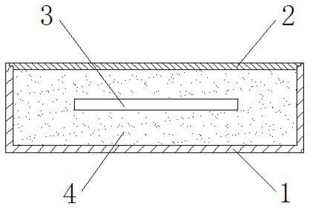
[0020] Such as figure 1 and figure 2 As shown, a photovoltaic junction box of the present invention includes a box body 1, a box cover 2, and an electrical component 3. The box body 1 and the box cover 2 form a cavity, and the electrical component 3 is arranged in the cavity; It is filled with insulating and heat-conducting filler, and the filler is quartz sand filler 4 . Quartz sand has high thermal conductivity and insulation properties, and has a large contact area with the arc, which is convenient for absorbing arc energy, so the arc can be cooled rapidly.

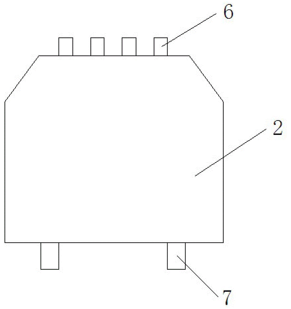
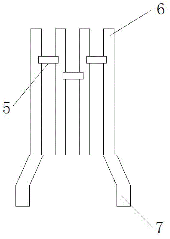
[0021] Such as image 3 As shown, the electrical assembly 3 includes a diode 5 , a conductive connecting piece 6 and a cable connecting piece 7 , the diode 5 is electrically connected between the conductive connecting pieces 6 , and the cable connecting piece 7 is electrically connected to the conductive connecting piece 6 . The terminal of the conductive connection piece 6 and the terminal of the cable connection ...

Embodiment 2

[0024] The rest are the same as in Embodiment 1, the difference is that one diode 5 is provided, two conductive connecting pieces 6 are provided, and the two conductive connecting pieces 6 are arranged at intervals to form a gap, and the diode 5 is arranged in the gap, and is connected to the two conductive connecting pieces 6. The conductive connecting piece 6 at the end is electrically connected. The cable connecting pieces 7 are electrically connected to the conductive connecting pieces at the left and right ends respectively.

[0025] The beneficial effect of adopting the technical solution is: by using quartz sand as the filling material, the requirements of insulation, heat conduction, sealing and resistance of the junction box are met, and at the same time, the production process is simple and convenient, and the production time is short, thereby effectively improving the production efficiency of the product. Quartz sand has high thermal conductivity and insulation prop...


PUM


Abstract

The invention discloses a photovoltaic junction box which comprises a box body, a box cover and an electrical component. The box body and the box cover form a cavity, the electrical component is arranged in the cavity, and the photovoltaic junction box further comprises packing materials for filling, insulting and radiating in the cavity, and the packing materials are quartz sand packing materials. By means of the technical scheme, the photovoltaic junction box has the advantages of meeting requirements of the junction box for insulation, radiating, sealing and resistance resisting by using quartz sand to serve as the packing materials, simultaneously being simple in manufacture process, convenient and short in manufacture time and further improving production efficiency of products.

Description

technical field [0001] The invention relates to solar photovoltaic modules, in particular to a photovoltaic junction box. Background technique [0002] The junction boxes currently on the market generally use a shell with an open back. There are electrical terminals in the shell to electrically connect the busbars at the output end of the solar cell template power with the input ends of the corresponding electrical terminals. The cables pass through one side of the shell. The holes extend into the housing and are electrically connected to the output hole on the other side of the electrical terminal. However, due to the existence of the electrical terminal, the junction box has a large volume and poor heat dissipation. The cable hole on the housing will cause the waterproof performance of the product. decline. For this reason, the sealed junction box made by potting glue uses the heat conduction, insulation, and resistance of silica gel to meet the needs of the junction box,...

Claims


Application Information

Patent Timeline
Patent Type & Authority Applications(China)
IPC IPC(8): H01L31/048H02S40/34
CPCY02E10/50
Inventor 许建明
Owner CHANGSHU FRIENDS CONNECTOR TECH
Why Eureka
Try Eureka