
Radiator for light-emitting diode (LED) lamp

A technology of LED lamps and radiators, applied in lighting and heating equipment, semiconductor devices of light-emitting elements, cooling/heating devices of lighting devices, etc. The effect of increasing fluidity and turbulence, increasing heat transfer area, and improving heat transfer coefficient

Active Publication Date: 2012-10-10
SOUTH CHINA UNIV OF TECH
View PDF2 Cites 4 Cited by
  • Summary
  • Abstract
  • Description
  • Claims
  • Application Information

AI Technical Summary

Problems solved by technology

[0002] LED lights have the advantages of high luminous efficiency, environmental protection, long life, strong directionality, and good color rendering. They are widely used in display, decoration, road and some special lighting fields. However, the photoelectric conversion efficiency of LEDs only reaches 10-25%. About 75-90% of the energy conversion heat, if the heat is not removed in time, it will lead to a decrease in the performance of the light source and affect the life of the LED
[0003] In the existing technology, designers usually increase the heat dissipation area to remove the heat and control the temperature of the lamp bead, but they do not consider the air flow of the heat dissipation structure; in addition, increasing the heat dissipation area makes the radiator bulky , wasting a lot of materials and increasing the cost of LED lamp production;
[0004] In the existing invention design, due to the consideration of material consumption, the open heat sink cooling method is generally adopted. For example, the patent number is CN201836839U utility model patent. During long-term use, a large amount of dust accumulates on the surface of the heat sink, which greatly reduces Heat exchange effect between heat sink and air

Method used


Image

  • Radiator for light-emitting diode (LED) lamp
  • Radiator for light-emitting diode (LED) lamp

Examples


Embodiment Construction

[0022] In order to better understand the present invention, the present invention will be further described below in conjunction with the accompanying drawings. It should be noted that the scope of protection of the present invention is not limited to the scope described in the embodiments.

[0023] The left-right direction of the drawings in the present invention is horizontal, and the front-back direction is vertical.

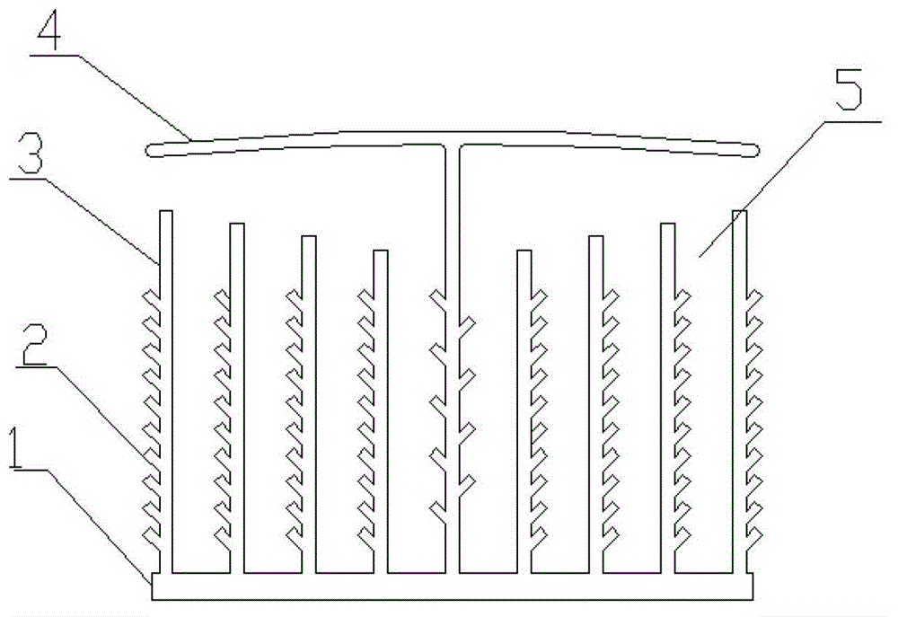
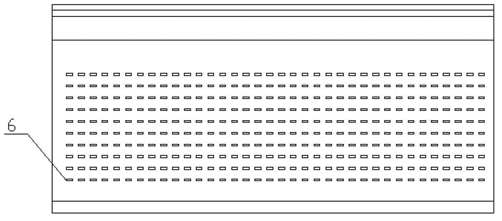
[0024] Such as figure 1 , 2 Shown, a kind of LED lamp radiator, it comprises heat dissipation substrate 1, small fin 2, large fin 3, dustproof cover 4, air flow channel 5 and window hole 6; Heat dissipation substrate 1 is square, thickness is 3 -5mm, the thickness can be changed; the large fins 3 are distributed longitudinally on the heat dissipation substrate 1 at intervals, preferably at a distance of 8-12mm, and the interval between every two large fins 3 forms an air flow channel 5; the dust cover 4 is provided Above the large fins 3, there is a distanc...


PUM

PropertyMeasurementUnit
Thicknessaaaaaaaaaa
Spacingaaaaaaaaaa

Abstract

The invention discloses a radiator for a light-emitting diode (LED) lamp. The radiator comprises a heat dissipation base plate, small fins, large fins, a dustproof cover, air flow channels and window holes, wherein the large fins are longitudinally distributed on the heat dissipation base plate at intervals; the space between every two large fins is provided with an air flow channel; the dustproof cover is arranged above the large fins and is 5 to 10mm away from the tops of the large fins; a plurality of small fins and window holes are formed in each large fin at intervals; acute angles or right angles are formed between the small fins and the large fins in the vertical direction; distances among each row of small fins and distances among each row of window holes are 2 to 10mm from top to bottom; and the dustproof cover is connected with the heat dissipation base plate. By the radiator, the heat dissipation area is increased, the fluidity of air around the radiator in the longitudinal and horizontal directions is enhanced, and a heat exchange coefficient between a heat dissipation surface and the air is improved; and the radiator integrates a heat dissipation function, a dustproof function and a waterproof function and meets the requirement of secondary packaging of high-power LED lamps.

Description

technical field [0001] The invention relates to heat dissipation of high-power electronic products, in particular to a heat sink for LED lamps, which is especially suitable for heat dissipation of high-power LED lighting lamps. Background technique [0002] LED lights have the advantages of high luminous efficiency, environmental protection, long life, strong directionality, and good color rendering. They are widely used in display, decoration, road and some special lighting fields. However, the photoelectric conversion efficiency of LEDs only reaches 10-25%. About 75-90% of the energy conversion heat, if the heat is not removed in time, it will cause the performance of the light source to decline and affect the life of the LED. [0003] In the existing technology, designers usually increase the heat dissipation area to remove the heat and control the temperature of the lamp bead, but they do not consider the air flow of the heat dissipation structure; in addition, increasin...

Claims


Application Information

Patent Timeline
IPC IPC(8): F21V29/00F21Y101/02F21V29/77F21V29/83F21Y115/10
Inventor 李静姚泽民贺高明梁剧
Owner SOUTH CHINA UNIV OF TECH
Learn More