
Electric connector

A technology of electrical connectors and sockets, which is applied in the directions of connections, circuits, and parts of connecting devices, etc., can solve the problems of electrical connection failures between cables and electrical connectors.

Inactive Publication Date: 2012-10-03
林雅萍
View PDF5 Cites 3 Cited by
  • Summary
  • Abstract
  • Description
  • Claims
  • Application Information

AI Technical Summary

Problems solved by technology

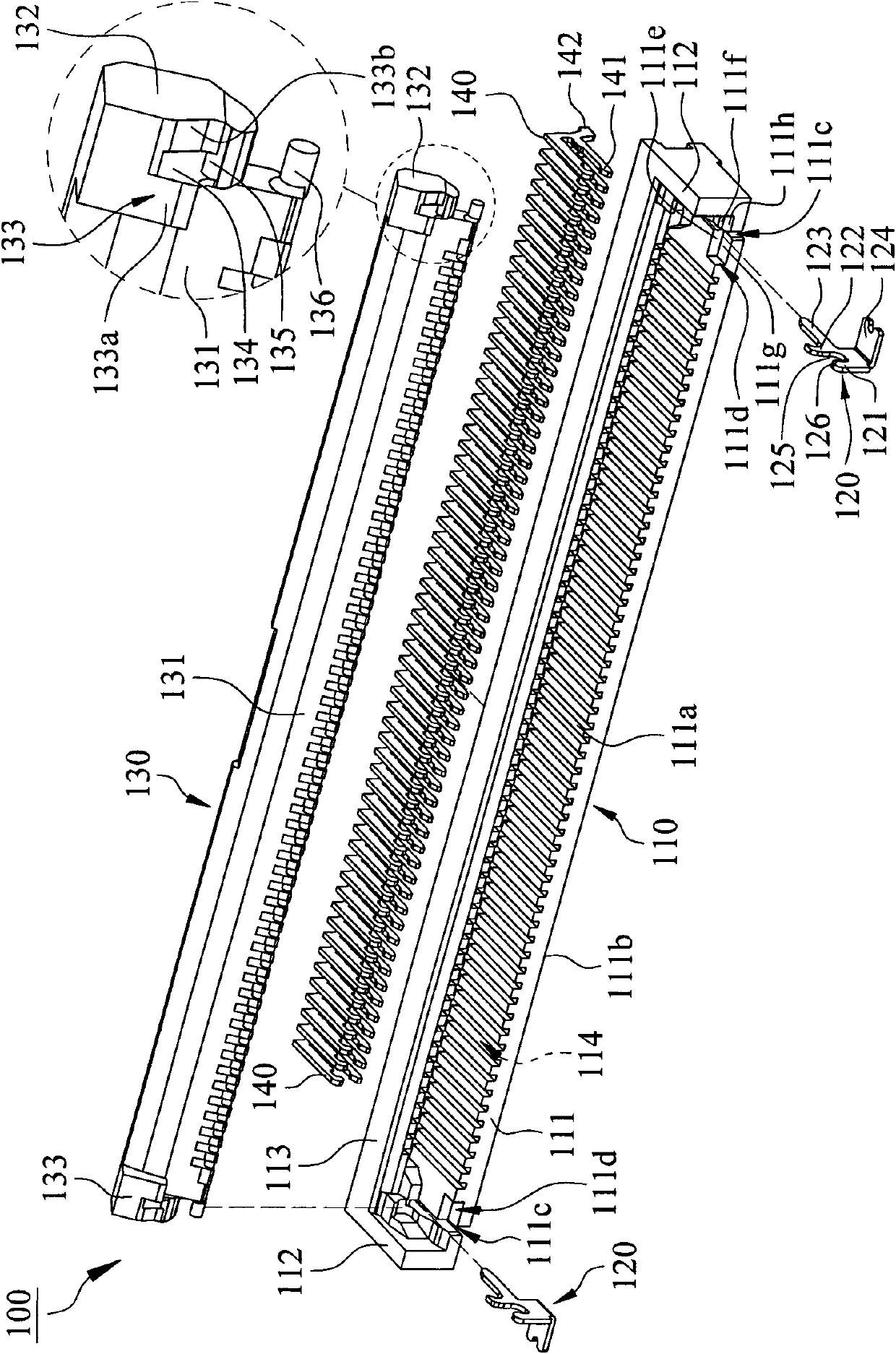
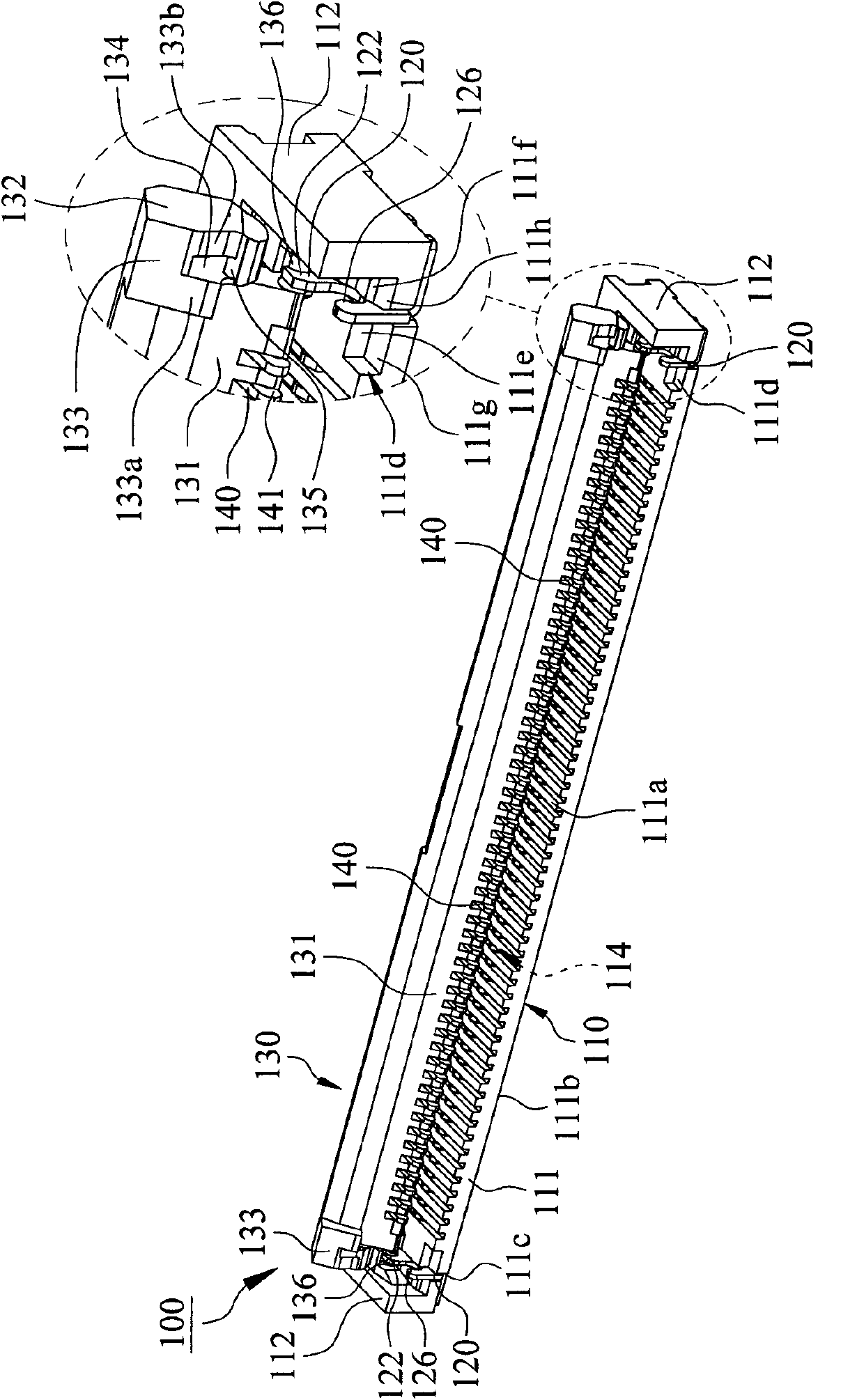
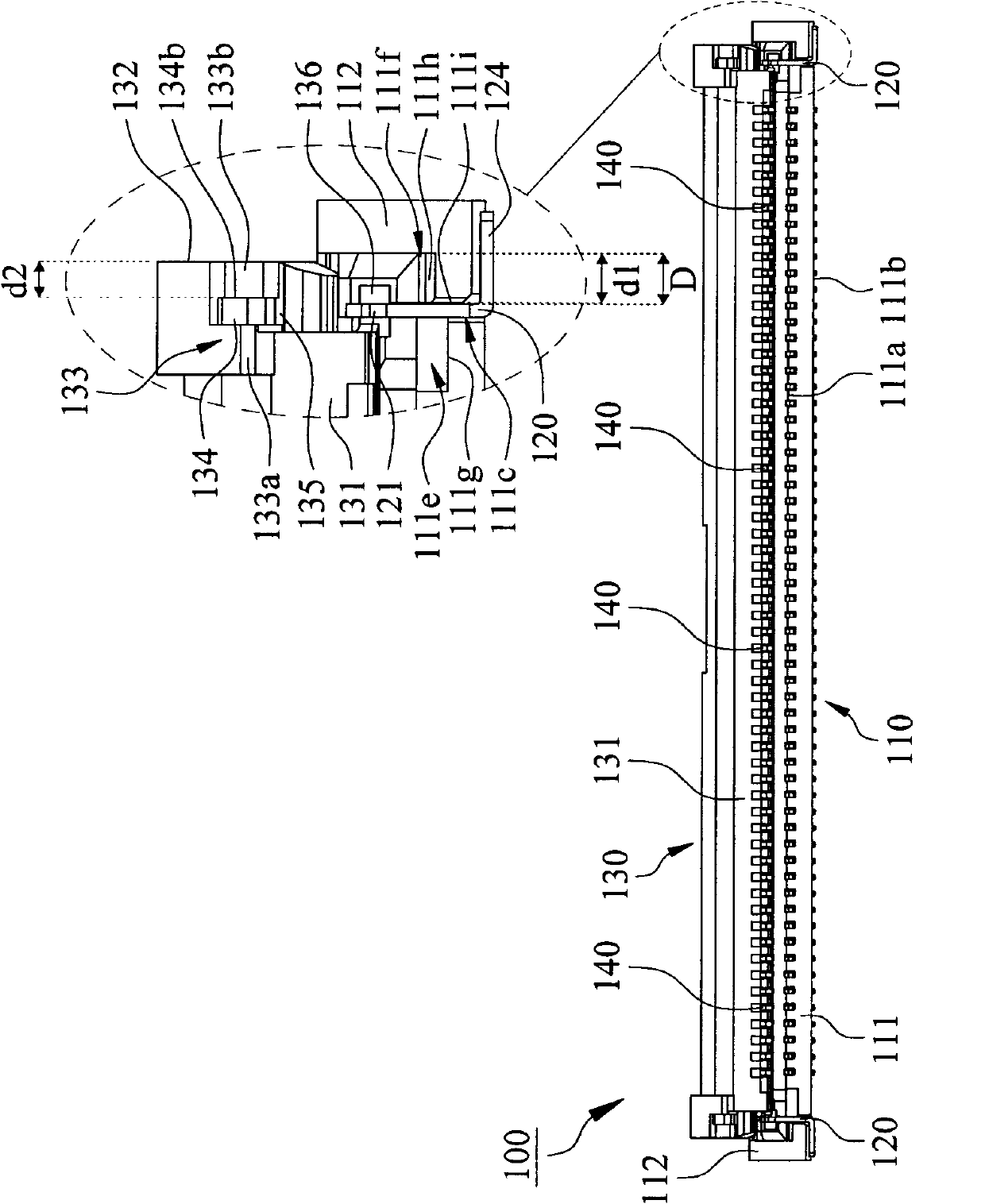
[0004] The main purpose of the present invention is to provide a novel structure by overcoming the deformation of the cover body or the longitudinal wall in the prior art, resulting in the failure of the cover body to be fastened to the longitudinal wall so that the electrical connection between the cable and the electrical connector fails. The electrical connector, the technical problem to be solved is to make it possible to increase the pressing strength of the cover body to the insulating body, so as to prevent the cable from falling off and prevent the cover body from being deformed, which is very suitable for practical use.

Method used


Image

  • Electric connector
  • Electric connector
  • Electric connector

Examples


Embodiment Construction

[0058] In order to further explain the technical means and effects of the present invention to achieve the intended purpose of the invention, the specific implementation, structure, features and effects of the electrical connector proposed according to the present invention will be described below in conjunction with the accompanying drawings and preferred embodiments. Details are as follows.

[0059] The aforementioned and other technical contents, features and effects of the present invention will be clearly presented in the following detailed description of preferred embodiments with reference to the drawings. Through the description of the specific implementation mode, a more in-depth and specific understanding of the technical means and effects adopted by the present invention to achieve the intended purpose can be obtained. However, the accompanying drawings are only for reference and description, and are not used to explain the present invention. be restricted.

[0060...


PUM


Abstract

The invention relates to an electric connector, which comprises an insulation body, two fixed terminals, a cover body and a plurality of connection terminals, wherein the insulation body is provided with a base plate, two longitudinal walls and an accommodating space; two insertion slots are formed on the base plate; a first distance is reserved between each insertion slot and each longitudinal wall; the fixed terminals are arranged in the insertion slots and provided with buckling parts; the buckling parts are protruded from an upper surface of the base plate; a transverse distance is reserved between each buckling part and each longitudinal wall; the cover body is provided with a pressing surface, two side faces, two limiting protruded parts, two buckling slots respectively formed on the limiting protruded parts and two buckling rods respectively arranged in the buckling slots; a second distance is reserved between each buckling slot and each side face; the buckling parts are buckled on the buckling rods; and the connection terminals are inserted into the insulation body. According to the electric connector, the pressing intensity of the cover body on the insulation body can be improved; a flat cable can be prevented from falling down; and the cover body can be prevented from being deformed.

Description

technical field [0001] The invention relates to an electrical connector, in particular to an electrical connector which prevents deformation of a cover body, falling off of a cable and increases pressing strength. Background technique [0002] see Figure 13 As shown, it is a perspective view of a combined structure of an existing conventional electrical connector combined with a row of wires. A conventional electrical connector 10 includes an insulating body 11, a cover 12 and a plurality of terminals 13, the insulating body 11 has a bottom plate 11a and two side walls 11b, and the terminals 13 are arranged on the The bottom plate 11a of the insulating body 11, each of the side walls 11b is provided with a card slot 11c, the cover 12 has two side surfaces 12a and two protruding points 12b protruding from the side surfaces 12a respectively, when the cover 12 covers the When the insulating body 11 is used, the bump 12b of the cover 12 is inserted into the slot 11c of the ins...

Claims


Application Information

Patent Timeline
Patent Type & Authority Applications(China)
IPC IPC(8): H01R13/502H01R13/42H01R13/62
Inventor 林雅萍
Owner 林雅萍
Learn More