
Robot steering engine with flexible characteristic

A robot and characteristic technology, applied in the field of robots, can solve the problems of troublesome installation and disassembly, and the rigidity of the elastic part cannot be adjusted, so as to reduce the space, realize the compliant drive, and ensure the work performance.

Inactive Publication Date: 2012-10-03
HANGZHOU DIANZI UNIV
View PDF10 Cites 8 Cited by
  • Summary
  • Abstract
  • Description
  • Claims
  • Application Information

AI Technical Summary

Problems solved by technology

The stiffness of the elastic part of the steering gear cannot be adjusted, and is only related to the stiffness of the coil spring itself; if you want to obtain a different stiffness area, you must replace all the springs, which is troublesome to install and disassemble

Method used


Image

  • Robot steering engine with flexible characteristic
  • Robot steering engine with flexible characteristic
  • Robot steering engine with flexible characteristic

Examples


Embodiment 1

[0042] Embodiment one, such as Figure 3-6 shown.

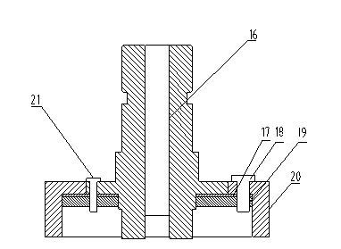
[0043] A cross-sectional view of a flexible gear 15 preloaded with a single-plate torsion spring. The flexible gear 15 is composed of a first hub 16, a first washer 17, a first screw 18, a first leaf torsion spring 19, a ring gear 20, a second Screw 21 forms.

[0044] The inner diameter of the ring gear 20 is the same as the outer diameter of the first hub 16, and the two are installed with a clearance fit. A threaded hole is opened on the ring gear 20 near the tooth root, and a threaded hole is also opened on the first wheel hub 16 near the output shaft. A first gasket 17 and a first leaf torsion spring 19 are installed between the inner surface of the first hub 16 and the first ring gear 20, wherein the first leaf torsion spring 19 is located below the first gasket 17; The gasket 17 and the first torsion spring 19 are positioned and installed with the first ring gear 20 and the first hub 16 respectively through the first s...

Embodiment 2

[0047] Embodiment two, such as Figure 7-10 shown.

[0048] A cross-sectional view of a flexible gear 15 preloaded with two torsion springs. The flexible gear 15 consists of a second hub 30, a third screw 31, a second washer 32, a second torsion spring 33, a fourth screw 34, a second The three-piece torsion spring 35 and the second ring gear 36 are formed.

[0049] The inner diameter of the second ring gear 36 is the same as the outer diameter of the second wheel hub 30, and the two are installed with a clearance fit.

[0050] The second ring gear 36 has a threaded hole and a through hole near the tooth root, and the second hub 30 has a boss structure near the output shaft. A second spacer 32 is installed between the second leaf type torsion spring 33 and the third leaf type torsion spring 35, and the three are placed below the ring gear 36, with threaded holes and through holes on it, through the third The screw 31 and the fourth screw 34 are positioned and installed.

[...


PUM


Abstract

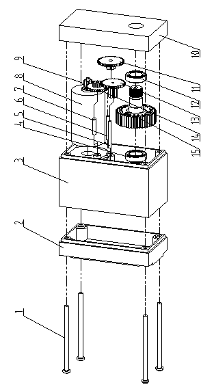
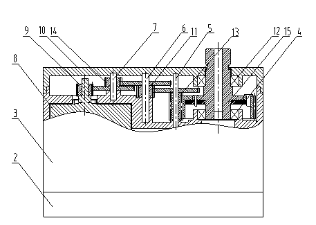
The invention relates to a robot steering engine with a flexible characteristic. The rigidity of the conventional device cannot be adjusted, so that the conventional device cannot meet the increasing requirement on a robot. The robot steering engine comprises long screws, a bottom cover, a shell, a motor, a motor gear, a top cover, an upper bearing, a lower bearing, a plurality of gear groups and a flexible gear, wherein the bottom cover, the shell and the top cover are connected with one another through the long screws to form a closed space; the motor, the motor gear, the upper bearing, the lower bearing, a plurality of gear groups and the flexible gear are arranged in the closed space; the motor gear is arranged on an output shaft of the motor; the motor gear drives the flexible gear to rotate through the gear groups; and the flexible gear is movably matched with the top cover through the upper bearing and movably matched with the shell through the lower bearing. By the torsional spring sheet type flexible structure, the space occupied by an elastic element is greatly reduced; and the robot steering engine is favorable for minimization and lightening of joints of the robot.

Description

technical field [0001] The invention belongs to the technical field of robots, and relates to a robot steering gear with compliance characteristics. Background technique [0002] With the continuous development of robots, the interaction between robots and humans is getting closer and closer, from the traditional industrial environment to the daily life of human beings. [0003] According to the principle of bionics, the movement of the robot imitates that of humans through joints. Each joint is consistent with the degree of freedom of each joint of the human being on the basis of accurate control. In order to achieve precise position control and specific trajectory tracking, traditional robot joint drive structures and algorithms are designed with high rigidity, resulting in poor safety and environmental adaptability, and high energy consumption. This requires the joint drive system of the new generation of robots to have certain compliance characteristics. [0004] In o...

Claims


Application Information

Patent Timeline
Patent Type & Authority Applications(China)
IPC IPC(8): B25J17/00
Inventor 周建军林阿斌张亚平
Owner HANGZHOU DIANZI UNIV
Learn More