
Flange mould system of shell branch hole of high-voltage switch

A technology of high-voltage switches and flanging molds, which is applied in the direction of forming tools, manufacturing tools, metal processing equipment, etc., can solve the problems that the ideal fit of splines cannot be guaranteed, the damage of tie rods will be aggravated, and the shell flanging will be cracked, etc. Good edge effect, reduce processing difficulty, and improve the effect of using strength

Inactive Publication Date: 2014-12-10
CHINA NAT HEAVY MACHINERY RES INSTCO
View PDF5 Cites 0 Cited by
  • Summary
  • Abstract
  • Description
  • Claims
  • Application Information

AI Technical Summary

Problems solved by technology

In addition, there are three layers of external splines, which can theoretically increase the contact area between the tie rod and the punch, thereby increasing the strength of the tie rod, but in the actual flanging process, it cannot be guaranteed that each layer of splines between the tie rod and the punch is ideal Cooperate, the contact between the two often becomes a point contact, and the long-term use will intensify the damage to the tie rod
[0004] In addition, the original fillet design of the convex and concave dies is not standardized, there is no unified standard, and it is often very random, resulting in the shell flanging prone to cracking, vertical edges are not straight and other undesirable phenomena

Method used


Image

  • Flange mould system of shell branch hole of high-voltage switch
  • Flange mould system of shell branch hole of high-voltage switch
  • Flange mould system of shell branch hole of high-voltage switch

Examples


Embodiment Construction

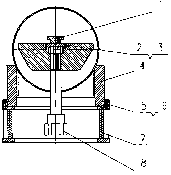
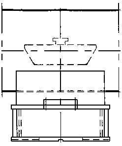
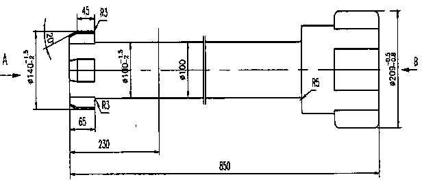
[0024] Examples are attached Figure 1 to Figure 9 As shown, it at least includes a wheel mold handle 1, a cover 2, a punch 3, a die 4, a right block 5, a left block 6, a die seat 7 and a pull rod 8. The mold handle 1 is connected with the punch 3 through a connector, and the material of the tie rod 8 is No. 45 steel, so as to improve the use strength of the tie rod from the material. The outer spline on the top end of the tie rod is changed from the original three layers to one layer. This design can ensure that the spline fit between the tie rod and the punch is always in surface contact, thereby improving the force of the tie rod during the flanging process. The top and bottom of the tie rod 8 are respectively processed with external splines. The top end is inserted into the internal spline groove of the punch 3 and then rotated 45° to engage with the punch. Connected together, the die 4 and the die base 7 are assembled together through the card slots with clearance fit, t...


PUM


Abstract

The invention belongs to a device of a flange production process of a cylindrical (shell) branch hole of aluminum and steel materials and particularly relates to a flange mould system of a shell branch hole of a high-voltage switch. The flange mould system is characterized in that: a mould handle is connected with a convex mould through a connecting piece; external splines are respectively machined at the top end and the bottom end of a pull rod; the top end of the pull rod is inserted into a spline groove in the convex mould and then rotates for 45 degrees to be clamped with the convex mould; the bottom part of the pull rod is inserted into a spline groove in an oil cylinder piston and then rotates for 45 degrees to be clamped with a main oil cylinder; a concave mould is clamped with a concave mould seat through clamping grooves which are in a clearance fit and two ends of the concave mould are fixed by a right baffling block and a right baffling block; the concave mould seat is fixed on a cross-shaped positioning key on a main worktable; a shell is placed on the concave mould to be subjected to alignment; and the convex mould is placed on an inserting head at the front end of a mechanical movable arm. The flange mould system has the advantages of reasonable and standard design, simplicity in machining and reliability in use; and the undesirable effects that a shell flange is easy to crack, a vertical edge is not straight, and the like are solved.

Description

technical field [0001] The invention belongs to the flanging production process of the branch hole of the cylindrical body (shell) made of aluminum and steel, which can realize the cold flanging of the cylinder body directly in the flanging process, without the need of preheating the cylinder body, once The invention relates to a device capable of realizing flanging process with good flanging effect, in particular to a flanging mold system for a branch hole of a high-voltage switch case. Background technique [0002] The flanging mold device of the branch hole of the cylinder (shell) made of aluminum and steel for GIS products is mainly used for the flanging of the branch hole of the cylinder (shell) of high-voltage switch GIS products made of aluminum and steel so that it can be used Require. [0003] Usually, the tie rod structure of the original flanging mold device is processed into an external spline (spline 360°quadrates) at the end of the rod, and three layers are di...

Claims


Application Information

Patent Timeline
Patent Type & Authority Patents(China)
IPC IPC(8): B21D37/10B21D19/00
Inventor 郝瑾马波郝乐刘畅成法坤
Owner CHINA NAT HEAVY MACHINERY RES INSTCO
Learn More