


Quick Research
Generate reliable direction feasibility study reports for your R&D in just a few steps.

Technical Q&A
Discover and master advanced knowledge NOW. Basics, ideas, possibilities, all at once.

Find Solutions
As an expert in R&D theories, this can generate solutions to your technical problems instantly.

Evaluate Feasibility
Analyze your overall solution with one click, know your potential R&D risks in advance.

Monitor Landscape
Get weekly tech updates, stay abreast of the latest tech innovations and key insights.
Improved method for characterizing oil or gas reservoir evolution over time
A technology for reservoir characterization, applied in seismic signal processing and other directions, which can solve problems such as limiting the effectiveness of reservoir engineers
- Summary
- Abstract
- Description
- Claims
- Application Information
AI Technical Summary
Problems solved by technology
Method used
Image

Examples
Embodiment Construction
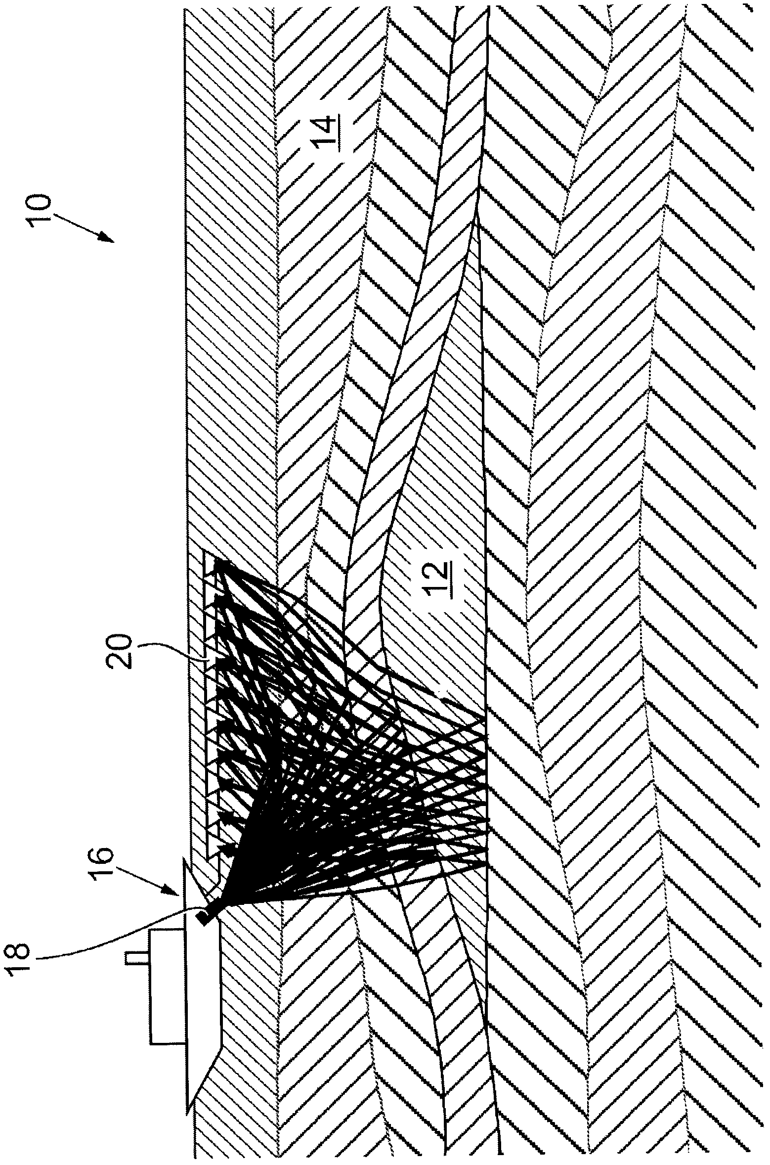
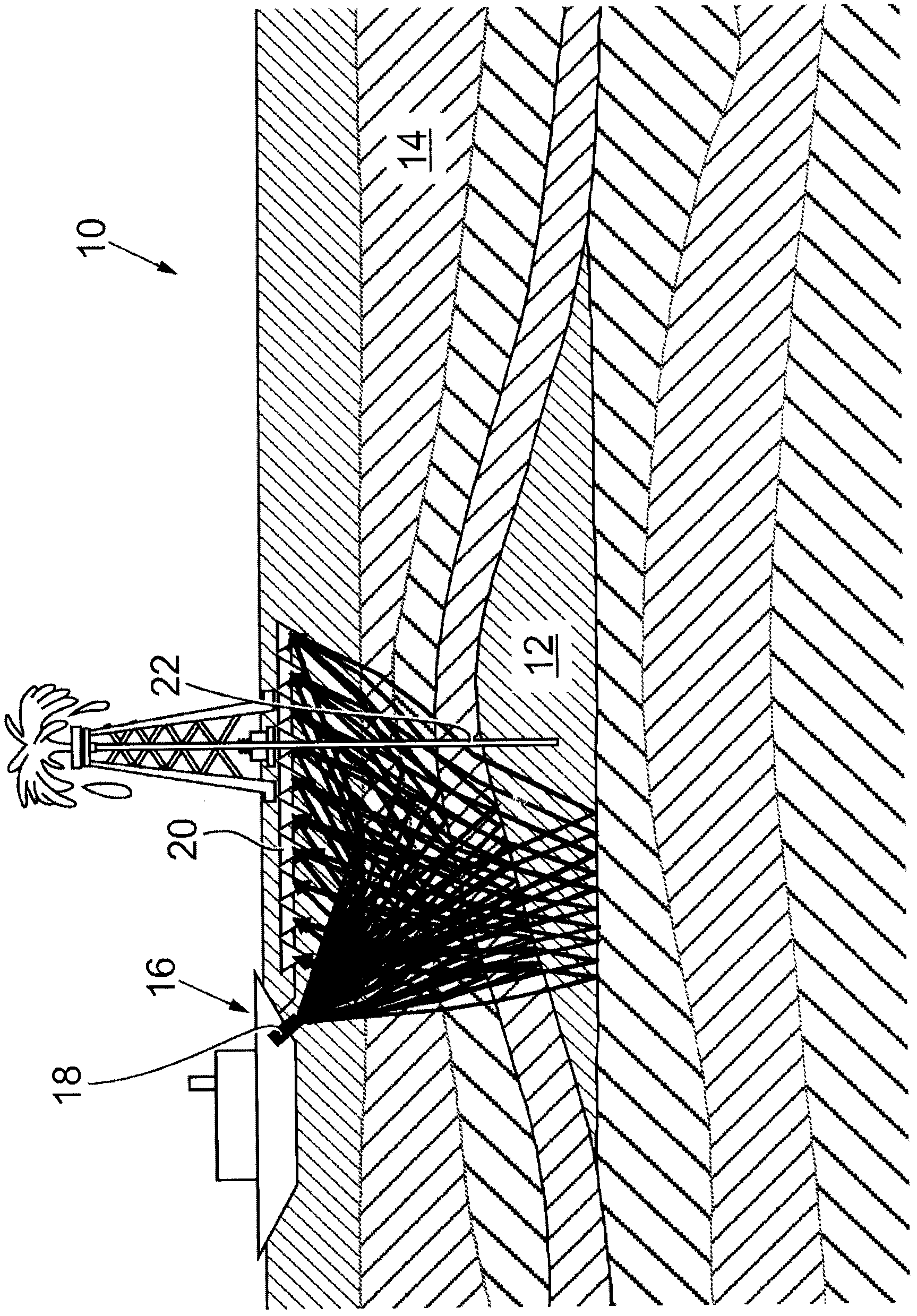
[0054] first reference Figure 2a and Figure 2b , shows a reservoir, generally indicated by reference numeral 10 , containing hydrocarbons 12 in the subsurface 14 . A sonar transmitter 18 and receiver array 20 are located on a survey vessel 16 , which is the source of sound, and which surveys by navigating over the reservoir 10 . The first or initial survey ( Figure 2a ) can be referred to as a base survey and is usually carried out during the exploration phase before production begins.
[0055] A base survey of the reservoir 10 provides a collection of seismic traces at a first time T. For a given seismic trace, the base survey provides the amplitude b(t) as a function of time t; where, with the value t i The set (i is the index) samples the digitally recorded and digitally processed traces; a typical trace length corresponds to about 1000 samples. Then, the seismic traces are processed as values b(t i ) or b i collection.
[0056] To extract hydrocarbons 12, one ...
PUM
 Abstract
Description
Claims
Application Information
 - R&D Engineer
- R&D Manager
- IP Professional
- Industry Leading Data Capabilities
- Powerful AI technology
- Patent DNA Extraction
Browse by: Latest US Patents, China's latest patents, Technical Efficacy Thesaurus, Application Domain, Technology Topic, Popular Technical Reports.
© 2024 PatSnap. All rights reserved.Legal|Privacy policy|Modern Slavery Act Transparency Statement|Sitemap|About US| Contact US: help@patsnap.com