
Apparatus for controlling electric oil pump

A technology for electric oil pumps and control devices, which is applied in pump control, pumps, pump testing, etc., and can solve problems such as reduced pump resistance and reduced pump load difference

Inactive Publication Date: 2012-09-26
HITACHI ASTEMO LTD
View PDF6 Cites 19 Cited by
  • Summary
  • Abstract
  • Description
  • Claims
  • Application Information

AI Technical Summary

Problems solved by technology

[0003] However, in the case where the piping of the hydraulic system is open to the atmosphere or for the purpose of lubrication and cooling, in an electric oil pump with low pump resistance, the viscosity of the oil decreases due to temperature rise, resulting in a decrease in pump resistance. The difference in pump load (motor current) decreases, so it is difficult to determine whether the resulting decrease in load is caused by idling or by a decrease in oil viscosity.

Method used


Image

  • Apparatus for controlling electric oil pump
  • Apparatus for controlling electric oil pump
  • Apparatus for controlling electric oil pump

Examples


Embodiment Construction

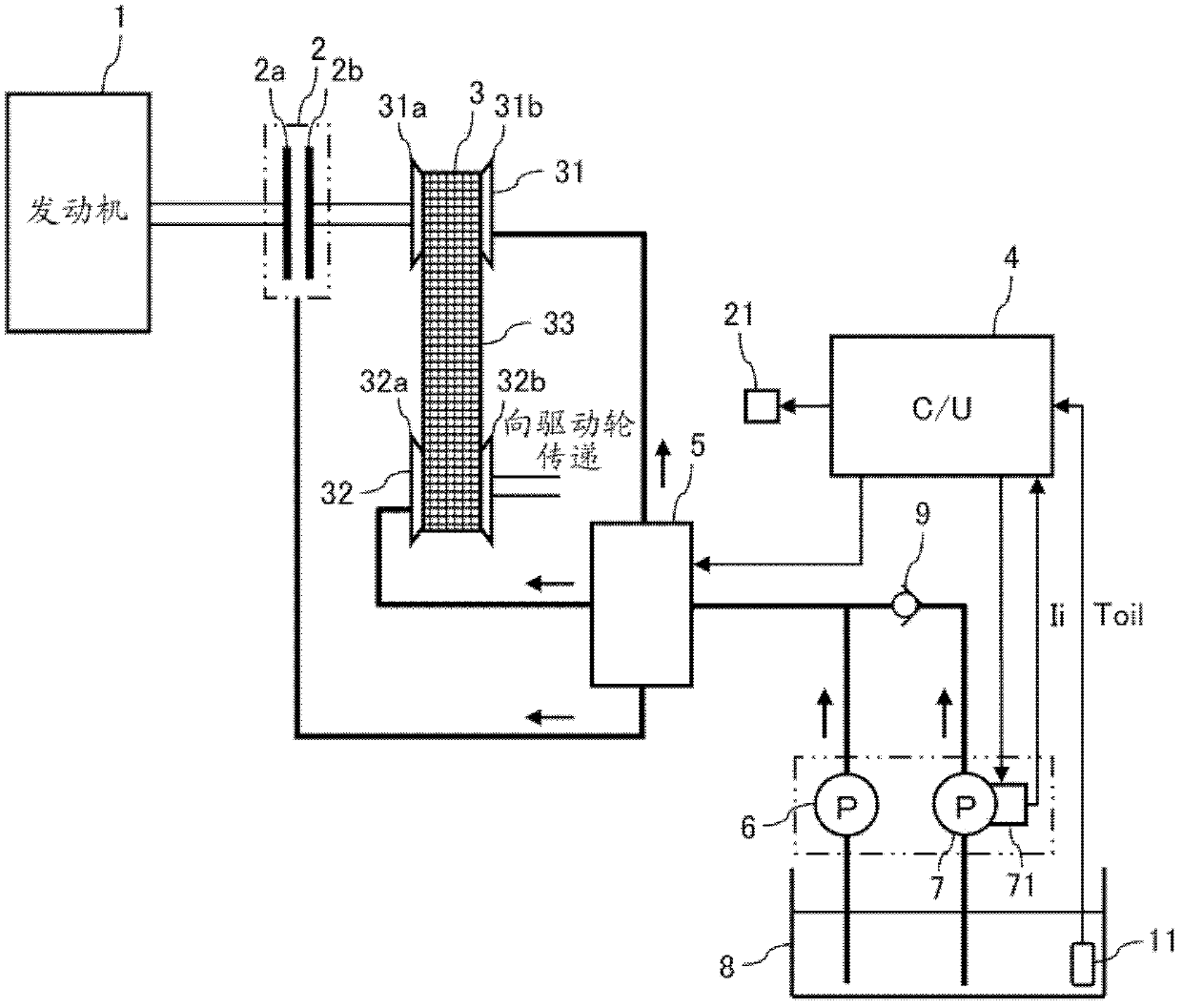
[0022] figure 1 It is a configuration diagram of a vehicle transmission system having the control device 4 of the electric oil pump 7 according to an embodiment of the present invention.

[0023] In the present embodiment, the internal combustion engine (hereinafter referred to as "engine") 1 constitutes the driving source of the self-driving vehicle, and the crankshaft is connected to the unillustrated forward and reverse switching mechanism for switching the forward and reverse of the vehicle via the starting clutch 2 and the reverse. Step transmission 3 is connected.

[0024] The starting clutch 2 is a wet multi-plate clutch in this embodiment ( figure 1 For convenience of description, only a pair of clutch plates are shown). When the vehicle starts, the clutch plates 2a and 2b on the input side and the output side are coupled by receiving the oil supply, and the output torque of the engine 1 is transmitted to the continuously variable transmission 3.

[0025] The continuously var...


PUM


Abstract

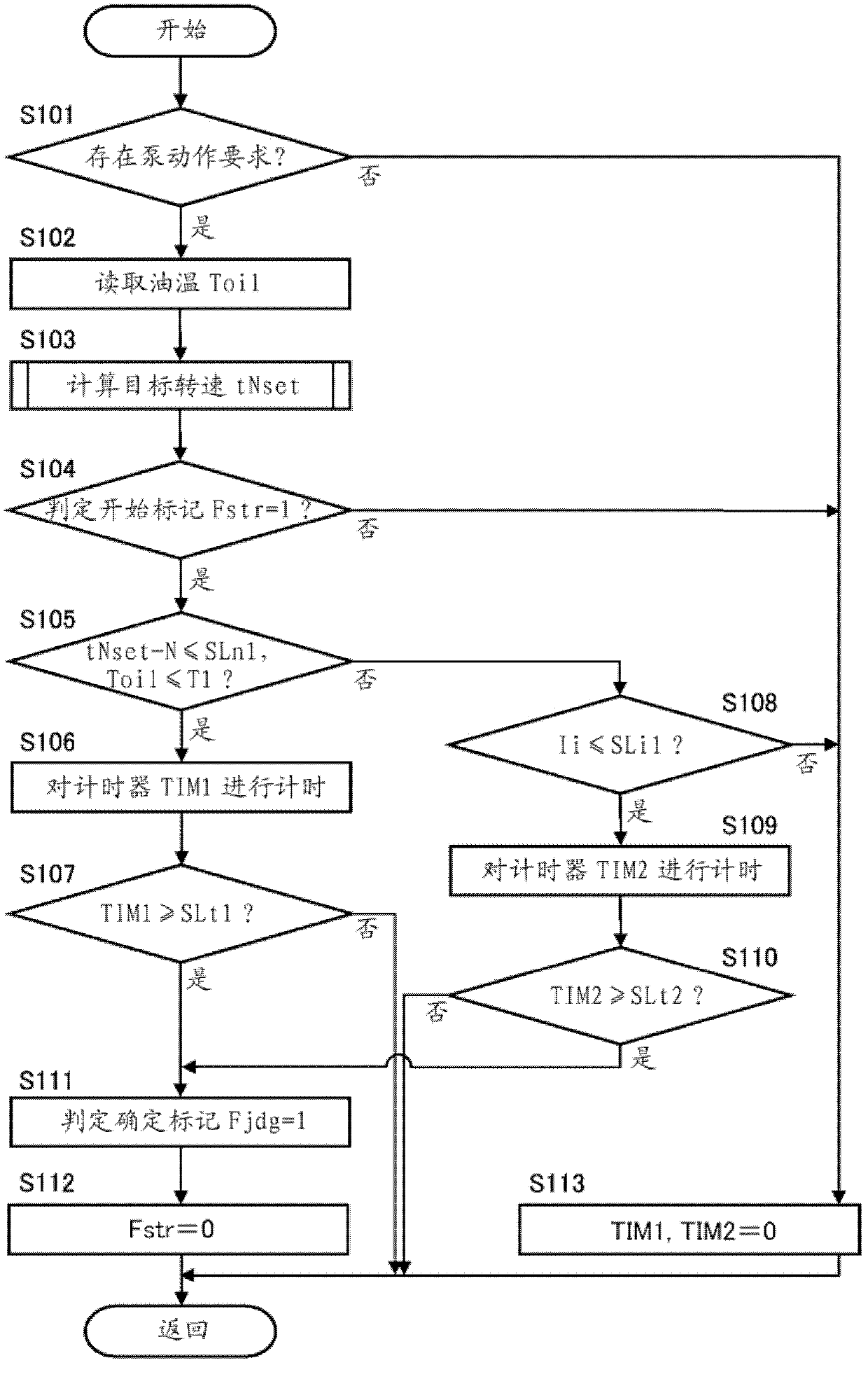
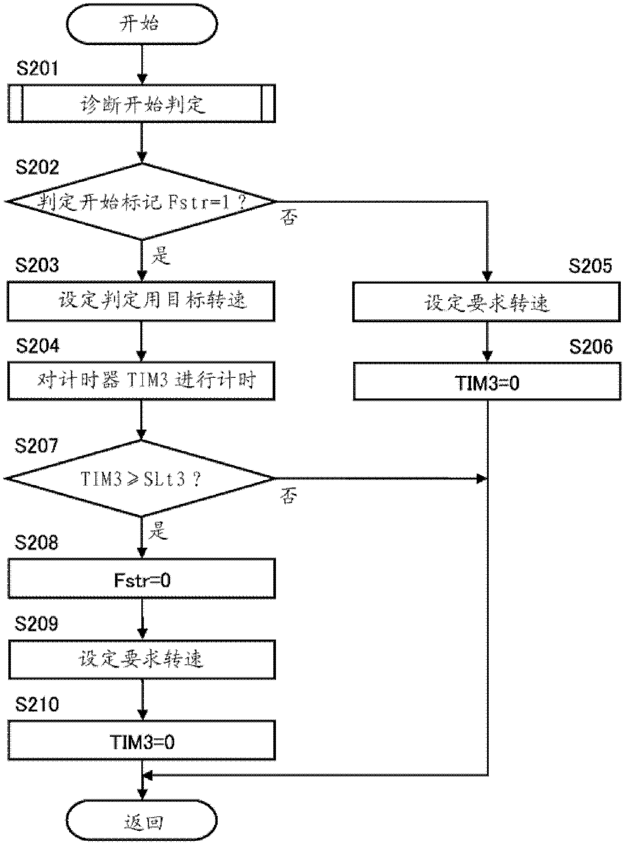
The invention in one aspect, provides an apparatus for controlling an electric oil pump that can determine the occurrence of idling even in a region in which determination based on a load of the electric oil pump becomes difficult. The apparatus for controlling an electric oil pump according to one embodiment of the invention sets a target number of revolutions for determination tNset higher than a required number of revolutions tNreq corresponding to an operation request of the electric oil pump, and executes control of an electric motor so that the number of revolutions N of the electric oil pump approaches the target number of revolutions for determination tNset. A load (phase current Ii) of the electric oil pump is detected while executing the control of the electric motor, and the occurrence of idling in the electric oil pump is determined based on a detected pump load (Inrm, IidI).

Description

Technical field [0001] The present invention relates to a control device and a control method of an electric oil pump using an electric motor as a power source. Background technique [0002] As a method of determining the idling of the electric oil pump, there is a method of using the motor current during pump operation. Japanese Patent Application Laid-Open No. 2009-299665 discloses that a motor current (for example, its drive command value) is detected during pump operation, and if the motor current is smaller than a predetermined value, it is determined that the idling has occurred. [0003] However, when the piping of the hydraulic system is open to the atmosphere or for lubrication or cooling purposes, in an electric oil pump with low pump resistance, the oil viscosity decreases due to temperature rise, resulting in a decrease in pump resistance, which is normal or idling. The difference in the pump load (motor current) of the pump is reduced, so it is difficult to judge whet...

Claims


Application Information

Patent Timeline
Patent Type & Authority Applications(China)
IPC IPC(8): F04B49/06
CPCF04B2203/0209F04B49/06F04B17/03
Inventor 木暮雅之
Owner HITACHI ASTEMO LTD
Learn More