
Display method and display device

A technology of a display device and a display method, applied in the field of 3D and 2D image display, can solve the problems affecting the user's viewing pleasure, blurred image dynamic images, low utilization rate of the display device, etc. Improve the effect of picture stability

Inactive Publication Date: 2012-09-19
BOE TECH GRP CO LTD +1
View PDF6 Cites 8 Cited by
  • Summary
  • Abstract
  • Description
  • Claims
  • Application Information

AI Technical Summary

Problems solved by technology

[0003] However, due to the lack of 3D image resources at present, the utilization rate of a display device that only performs 3D display is low. A display device with market competitiveness is capable of displaying both 2D images and 3D images, and can display 3D images according to customer needs. Display device for converting 3D image signal into 2D image signal for display
[0004] When implementing the technical solution of the present invention, the inventor found that the existing 2D video display technology has a relatively low minimum refresh rate, and there is a relatively serious video smear phenomenon, which causes the dynamic image of the image to be blurred and affects the viewing pleasure of the user.
[0005] At the same time, the inventor also found that the main problem of using 3D switching glasses to realize 3D display technology is that crosstalk is prone to occur during the scanning process of left and right eye images, that is, during scanning and displaying the left eye image, the left eye can observe part of the previous image. Frame the image of the right eye, similarly, when scanning and displaying the image of the right eye, the right eye can see part of the image of the left eye of the previous frame, so long-term viewing is easy to cause visual fatigue to the user

Method used


Image

  • Display method and display device
  • Display method and display device
  • Display method and display device

Examples


Embodiment 1

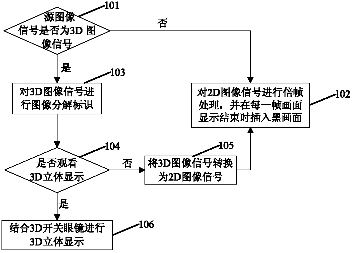
[0026] An embodiment of the present invention provides a display method, the display method comprising:

[0027] When it is determined that the source image signal is a 2D image signal, the source image signal is subjected to frame doubling processing, and a black image is inserted at the end of displaying each frame.

[0028] When it is judged that the source image signal is a 3D image signal, carry out image decomposition identification on the source image signal, if it is selected as 3D display, then combine with 3D switching glasses to perform 3D stereoscopic display; if it is selected as 2D display, then it will undergo image decomposition identification The original image signal is converted into a 2D image signal, subjected to frame multiplication processing, and a black image is inserted at the end of each frame display.

[0029] In the embodiment of the present invention, such as figure 1 As shown, the specific steps are as follows:

[0030] Step 101: Judging the so...

Embodiment 2

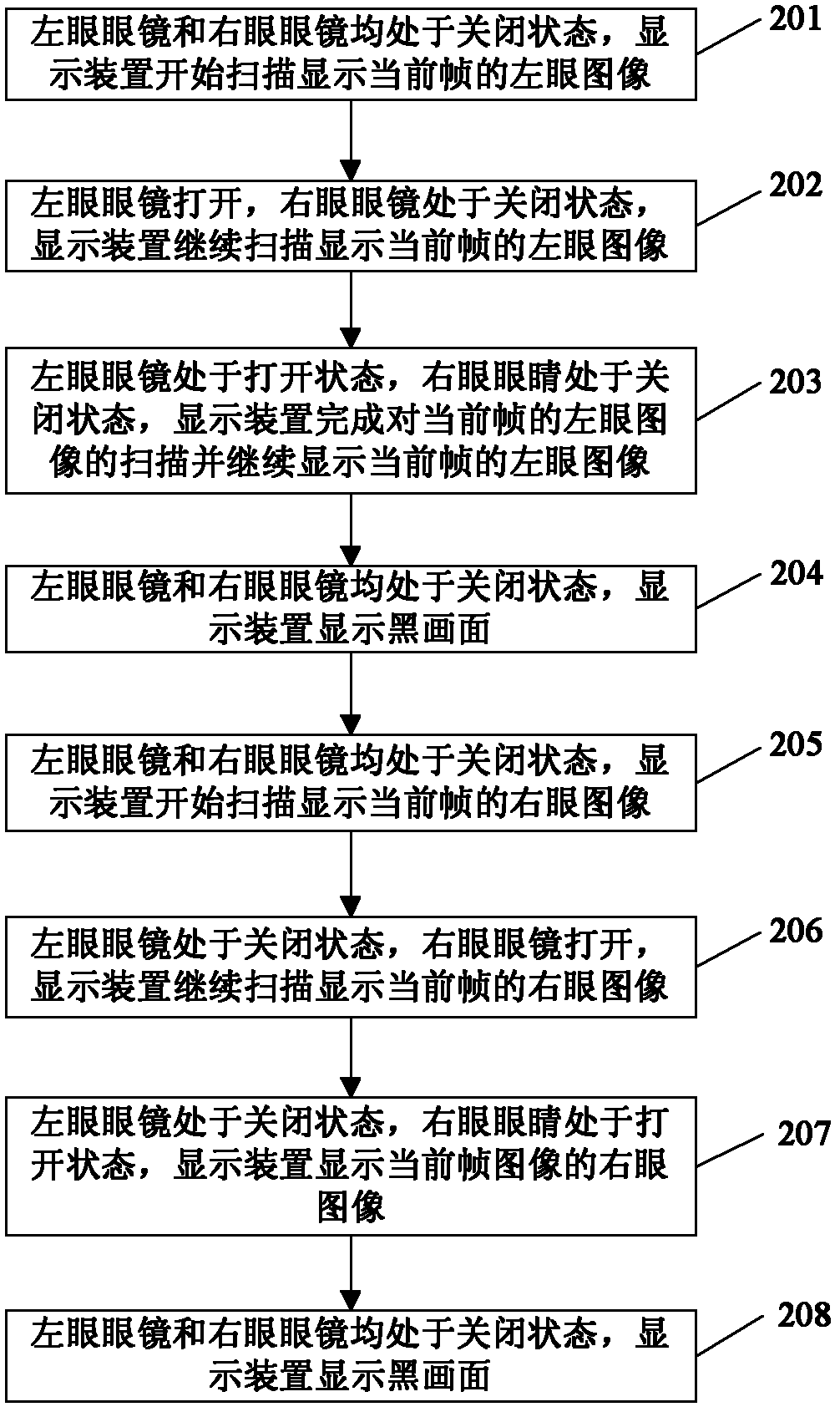
[0048] An embodiment of the present invention provides a display method, which is a 3D stereoscopic display method, such as figure 2 As shown, the display method includes:

[0049] When performing image decomposition and marking on the source image signal and combining with 3D switch glasses to perform 3D stereoscopic display, further, displaying a frame of 3D image includes eight moments:

[0050] Step 201: At the first moment, both the left-eye glasses and the right-eye glasses are closed, and the display device starts to scan and display the left-eye image of the current frame.

[0051] Step 202: At the second moment, the left-eye glasses are turned on and the right-eye glasses are closed, and the display device continues to scan and display the left-eye image of the current frame.

[0052] Step 203: At the third moment, the left-eye glasses are in the open state and the right-eye glasses are in the closed state, the display device finishes scanning the left-eye image of ...

Embodiment 3

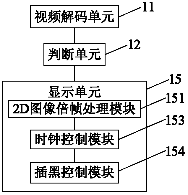
[0064] An embodiment of the present invention provides a display device, which includes:

[0065] The video decoding unit 11 is configured to decode the source image signal.

[0066] A major challenge with digital video today is the large amount of data required to store or transmit raw or uncompressed video. Obviously, the storage or transmission of digital video needs to adopt compression technology. The purpose of video compression is to encode digital video - using as little space as possible while maintaining video quality.

[0067] A video decoding unit refers to a program capable of decompressing digital video. In daily life, video encoding and video decoding are widely used. For example in DVD (MPEG-2), in VCD (MPEG-1), in various satellite and terrestrial television broadcasting systems, on the Internet. Online video image materials are usually compressed using many different encoding units. Therefore, in the embodiment of the present invention, in order to enable...


PUM

PropertyMeasurementUnit
Refresh rateaaaaaaaaaa

Abstract

The embodiment of the invention discloses a display method and a display device, and relates to the field of three-dimensional (3D) and two-dimensional (2D) image display. If an input source signal is a 2D image signal, the 2D image signal is two-dimensionally displayed; and if the input source signal is a 3D image signal, the 3D image signal can be three-dimensionally or two-dimensionally displayed according to the needs and likes of a user. The problems of flicker and tailing of the conventional display device are solved, an image edge blur phenomenon of a rapid motion picture is eliminated, 'illusion' caused by the visual persistence of a human eye is corrected, and the stability of the picture is effectively improved; and a crosstalk phenomenon caused by the simultaneous display of a left-eye image and a right-eye image in the conventional active 3D technology is completely eliminated. The display method and the display device are applied to 3D and 2D image display.

Description

technical field [0001] The invention relates to the field of 3D and 2D image display, in particular to a display method and a display device. Background technique [0002] With the development of 3D display technology and the increase of 3D image content, consumers are more and more interested in products that can realize 3D display, and the demand is also more and more vigorous. At present, the relatively mature method of realizing 3D display is to use 3D polarized glasses or 3D switching glasses to allow the left and right eyes to receive image information with parallax from the display device, and the brain will start a process after receiving different image information with parallax. A complex processing system compares and mixes two sets of information. This process will bring a by-product—three-dimensional sense while generating the shape of the object. [0003] However, due to the lack of 3D image resources at present, the utilization rate of a display device that o...

Claims


Application Information

Patent Timeline
IPC IPC(8): H04N13/00
CPCG09G5/14H04N13/00H04N13/0497H04N13/0452H04N13/0438H04N13/341H04N13/356H04N13/398
Inventor 刘金良
Owner BOE TECH GRP CO LTD
Learn More