


Quick Research
Generate reliable direction feasibility study reports for your R&D in just a few steps.

Technical Q&A
Discover and master advanced knowledge NOW. Basics, ideas, possibilities, all at once.

Find Solutions
As an expert in R&D theories, this can generate solutions to your technical problems instantly.

Evaluate Feasibility
Analyze your overall solution with one click, know your potential R&D risks in advance.

Monitor Landscape
Get weekly tech updates, stay abreast of the latest tech innovations and key insights.
Composite metal ceramic tubular piezoelectric motor
A metal-ceramic composite and piezoelectric motor technology, applied in piezoelectric effect/electrostrictive or magnetostrictive motors, electrical components, generators/motors, etc., can solve problems such as complex structures and limited motor thrust
- Summary
- Abstract
- Description
- Claims
- Application Information
AI Technical Summary
Problems solved by technology
Method used
Image


Examples
Embodiment 1
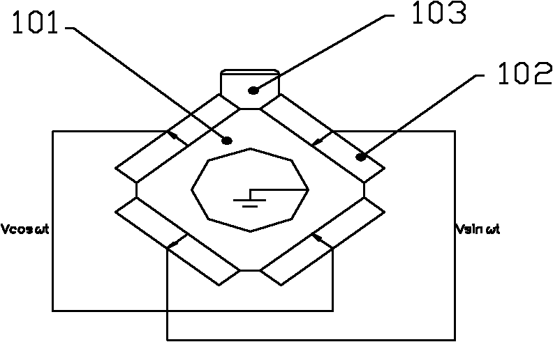
[0025] see figure 1 and 2 , The stator is provided with a metal tube 101, piezoelectric ceramics 102 (4 pieces), driving feet 103 and electrodes (two pairs). The cross section of the metal tube 101 is square, and the four edges 1011 of the metal tube 101 are facet transition edges, which can reduce the rigidity of the metal tube 101 . The center hole of the metal tube 101 is labeled 1010 . The four sides of the metal tube 101 are respectively symmetrically pasted with a piece of piezoelectric ceramic 102 using high-strength epoxy resin. The driving foot 103 is disposed on an edge 1011 of the metal pipe 101 , and the driving foot 103 is generally made of wear-resistant materials, such as alumina ceramics, hard alloy, and the like. The upper and lower surfaces of the piezoelectric ceramic 102 are full electrodes, which are polarized along the thickness direction, such as figure 2 indicated by the arrow. The polarization directions of two adjacent pairs of piezoelectric cera...
Embodiment 2
[0027] see image 3 , similar to that of Embodiment 1, the difference is that the driving foot 103 is located in the middle of the surface of one piezoelectric ceramic 102 out of the four piezoelectric ceramics 102 . Works the same. image 3 The rest of the labels in are correspondingly consistent with Example 1.
Embodiment 3
[0029] see Figure 4 and 5 , similar to Embodiment 2, the difference is that the stator is also provided with a clamping piece 100 and an elastic piece 104 , the holding piece 100 is bonded to the piezoelectric ceramic 102 , and the elastic piece 104 is bonded to the clamping piece 100 . Bonding with epoxy resin. Bonding enables the stator, the clamping member 100 and the elastic member 104 to form a one-piece structure. The function of the elastic member 104 is to exert a pre-tightening force on the driving foot 103 through the clamping member 100 and at the same time play the role of fixing the stator. The elastic member 104 is a leaf spring. The clamping piece 100 is clamped at the node position of the stator, and other parts of the stator are not in contact with the spring sheet 104, so that the vibration of the stator will not be affected. The position of the node depends on the adopted vibration mode. For example, if the first-order bending vibration mode is adopted,...
PUM
 Abstract
Description
Claims
Application Information
 - R&D Engineer
- R&D Manager
- IP Professional
- Industry Leading Data Capabilities
- Powerful AI technology
- Patent DNA Extraction
Browse by: Latest US Patents, China's latest patents, Technical Efficacy Thesaurus, Application Domain, Technology Topic, Popular Technical Reports.
© 2024 PatSnap. All rights reserved.Legal|Privacy policy|Modern Slavery Act Transparency Statement|Sitemap|About US| Contact US: help@patsnap.com