Air pipe connecting structure
A connection structure and air duct technology, applied in the direction of adjustable connections, pipes/pipe joints/fittings, passing components, etc., can solve problems such as strong vibration, interface misalignment, poor rigidity, etc., and achieve the effect of simple structure and reliable performance
- Summary
- Abstract
- Description
- Claims
- Application Information
AI Technical Summary
Problems solved by technology
Method used
Image
Examples
no. 1 example
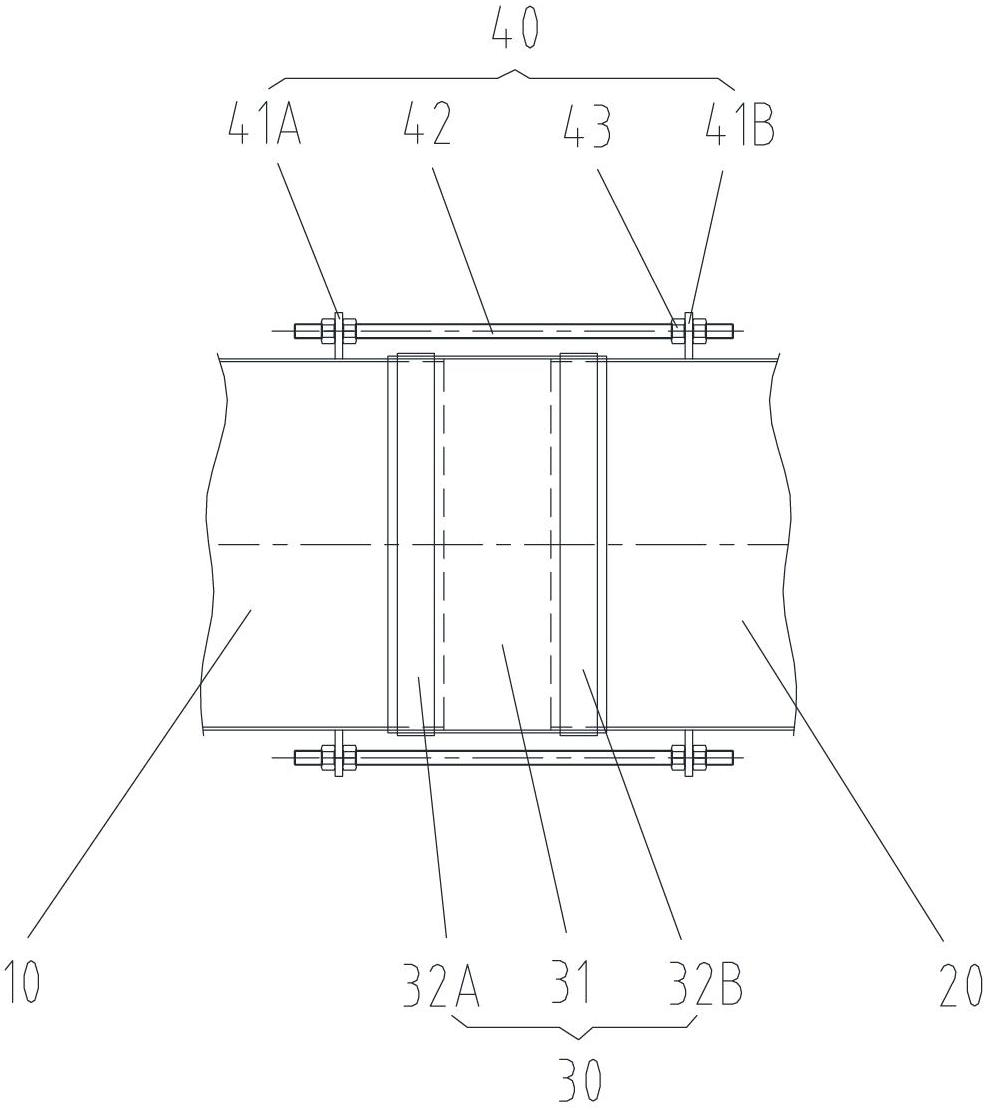
[0025] Such as figure 1 As shown, in the first embodiment, the soft interface 30 includes a connecting hose 31 , a first clamp 32A and a second clamp 32B. The first end of the connecting hose 31 is sleeved on the outside of the first air pipe 10 , and the second end is sleeved on the outside of the second air pipe 20 . The first clamp 32A is disposed outside the first end of the connecting hose 31 . The second clip 32B is disposed outside the second end of the connecting hose 31 . The first clamp 32A and the second clamp 32B clamp the two ends of the connecting hose 31 on the first air pipe 10 and the second air pipe 20, ensuring that the first air pipe 10 and the second air pipe 20 sealed connection.
[0026] The soft interface 30 of the first embodiment is only a specific example of the soft interface of the present invention, and the same soft interface form is also adopted in the second and third embodiments to be described below. The soft interface will not be describ...
no. 2 example
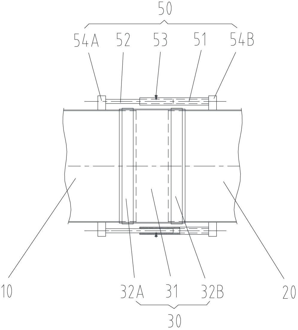
[0034] Such as figure 2 As shown, in the second embodiment, the first fixing part includes a first support member 54A, and the first support member 54A is welded to the outer wall of the first air duct 10 . The second fixing part includes a second support piece 54B, and the second support piece 54B is welded to the outer wall of the second air duct 20 . The adjustment part includes a hollow tube 51, a pin rod 52 and a set screw 53. One end of the hollow tube 51 is welded to one of the first support 54A and the second support 54B, and one end of the pin rod 52 is welded to the first support. 54A and the other of the second support member 54B, the other end of the pin rod 52 is slidingly fitted with the other end of the hollow tube 51, and the side wall of the hollow tube 51 matched with the pin rod 52 is provided with a threaded through hole, tightly Set screw 53 matches with threaded through hole.
[0035] Similar to the first embodiment, the rigid connection device may also ...
no. 3 example
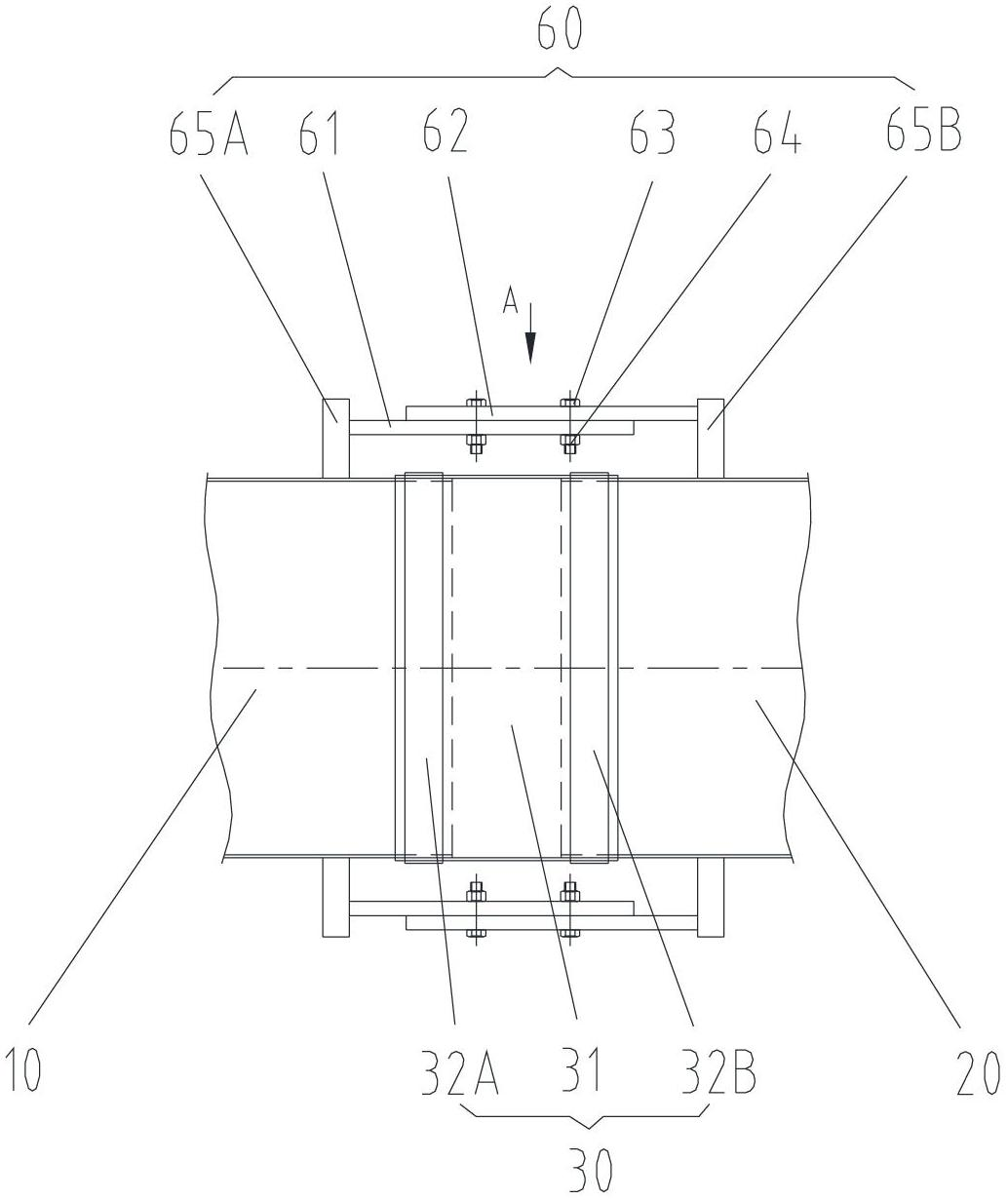
[0038] Such as image 3 As shown, in the third embodiment, the first fixing part includes a third support member 65A, and the third support member 65A is welded to the outer wall of the first air duct 10 . The second fixing part includes a fourth supporting piece 65B, and the fourth supporting piece 65B is welded to the outer wall of the second air duct 20 . The adjustment part includes a first connecting piece 61, a second connecting piece 62, at least one bolt 63 and at least one second nut 64. The first connecting piece 61 includes a first waist-shaped hole and one end is welded on the third supporting piece 65A. The two connecting parts 62 include a second waist-shaped hole and one end is welded on the fourth support member 65B, the first waist-shaped hole is set corresponding to the second waist-shaped hole, and the threaded end of each bolt 63 passes through the first waist-shaped hole Match with the second oblong hole and with a second nut 64 . Specifically, in the th...
PUM
 Abstract
Description
Claims
Application Information
 - R&D
- Intellectual Property
- Life Sciences
- Materials
- Tech Scout
- Unparalleled Data Quality
- Higher Quality Content
- 60% Fewer Hallucinations
Browse by: Latest US Patents, China's latest patents, Technical Efficacy Thesaurus, Application Domain, Technology Topic, Popular Technical Reports.
© 2025 PatSnap. All rights reserved.Legal|Privacy policy|Modern Slavery Act Transparency Statement|Sitemap|About US| Contact US: help@patsnap.com


