
Fan

A technology of wind turbines and synchronous generators, which is applied in wind turbines, wind turbine combinations, engines, etc., which can solve the problems of high manufacturing cost of wind turbine foundation equipment, unstable power generation quality, and poor power generation quality, and reduce manufacturing costs , Good power generation quality and light weight

Inactive Publication Date: 2012-09-19
SHANGHAI TIANDI RENHE INVESTMENT
View PDF0 Cites 9 Cited by
  • Summary
  • Abstract
  • Description
  • Claims
  • Application Information

AI Technical Summary

Problems solved by technology

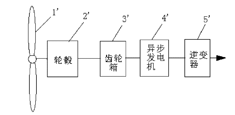
[0004] 1. The weight is heavy, because the gearbox 3' is more than 50 tons, and the inverter 5' is more than ten tons, close to more than 60 tons, resulting in a large weight of the fan and high manufacturing costs of the foundation equipment of the fan
[0005] 2. There are many components, because the existing structure needs to use the gearbox 3' and the inverter 5', both of which are large components, and are the two components that are most prone to problems in the fan. Due to the large number of components, lead to reduced reliability
[0006] 3. The quality of power generation is not good. Since the hub 2' and the gearbox 3' are rigidly connected, once the input fluctuates, it will affect the input end of the generator, and the quality of power generation will be unstable

Method used


Image

  • Fan
  • Fan
  • Fan

Examples


Embodiment Construction

[0016] The present invention will be further described below in conjunction with accompanying drawing.

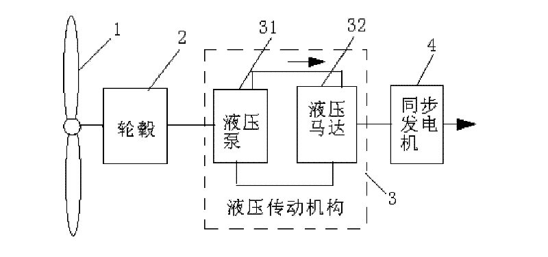
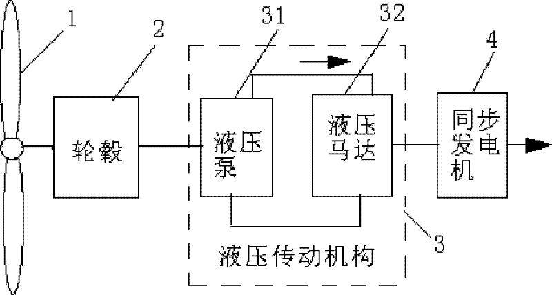
[0017] see figure 2 , the figure shows a fan of the present invention, including a blade 1 and a hub 2 connected to the blade 1, the blade 1 is installed on the hub 2, and also includes a hydraulic transmission mechanism 3 and a synchronous generator 4, the hydraulic transmission mechanism The input end of 3 is connected with the output end of hub 2 , and the output end of hydraulic transmission mechanism 3 is connected with synchronous generator 4 .

[0018] The hydraulic transmission mechanism 3 includes a closed-loop hydraulic pump 31 and a hydraulic motor 32 connected in series to the hydraulic pump 31 , the hydraulic pump 31 is connected to the output end of the hub 2 , and the output end of the hydraulic motor 32 is connected to the synchronous generator 4 .

[0019] Working principle: The hydraulic pump 31 drives the hydraulic motor 32, and then drives the synchron...


PUM


Abstract

The invention relates to a fan. The fan comprises a blade, a hub connected with the blade, a hydraulic transmission mechanism and a synchronous generator, wherein the blade is arranged on the hub; the input end of the hydraulic transmission mechanism is connected with the output end of the hub; and the output end of the hydraulic transmission mechanism is connected with the synchronous generator. The original gear box is replaced by the hydraulic transmission mechanism, so that the power generation frequency of the synchronous generator is 50Hz, inversion is avoided, direct Internet surfing is realized, and the fan has the advantages of light weight, a few parts and high reliability and power generation quality.

Description

technical field [0001] The invention relates to a fan, in particular to a fan with hydraulic transmission. Background technique [0002] see figure 1 , the figure shows the fan structure in the prior art, including sequentially connected blades 1', hub 2', gearbox 3', asynchronous generator 4', inverter 5', and blades 1' are installed on the hub 2' , the wheel hub 2' drives the gear box 3' to rotate, and the gear box 3' speeds up and then drives the asynchronous generator 4' to generate alternating current through the inverter 5'. [0003] The current fan structure has the following disadvantages: [0004] 1. The weight is heavy, because the gear box 3' is more than 50 tons, and the inverter 5' is more than ten tons, close to more than 60 tons, resulting in a large weight of the wind turbine and high manufacturing costs of the foundation equipment of the wind turbine. [0005] 2. There are many components, because the existing structure needs to use the gearbox 3' and the...

Claims


Application Information

Patent Timeline
Patent Type & Authority Applications(China)
IPC IPC(8): F03D9/00F16H39/02H02K7/18F03D9/25
CPCY02E10/722Y02E10/72Y02P70/50Y02P80/10
Inventor 张琪李易为张延迟杨宏坤施锦锦王恩强庄清
Owner SHANGHAI TIANDI RENHE INVESTMENT
Learn More