
Plastic circular weaving machine

A technology of circular looms and plastics, applied in circular looms, looms, textiles, etc., can solve the problems of weaving speed, power consumption constraints, increased equipment costs, and heavy load on the balance wheel, so as to reduce the failure rate and prevent cloth efficiency, increase the weaving speed and simplify the structure

Inactive Publication Date: 2012-09-19
HENGYI PLASTIC EQUIP MFG
View PDF7 Cites 4 Cited by
  • Summary
  • Abstract
  • Description
  • Claims
  • Application Information

AI Technical Summary

Problems solved by technology

[0003] First of all, when weaving woven fabrics with a diameter of less than 800mm, a circular loom with a four-shuttle structure or a plastic circular loom with a small six-shuttle structure is generally used, so its weaving speed and power consumption are subject to certain restrictions;
[0004] Secondly, in addition to the winding device, the current plastic circular loom is also equipped with a lifting device. The functions of the two are repeated, which complicates the structure of the equipment, brings inconvenience to the installation and commissioning of the equipment and increases the cost of the equipment;
[0005] Third, the main motor and the main transmission system of the current plastic circular loom have no braking device, so that the plastic circular loom does not respond in time when the plastic circular loom shuts down due to failure, resulting in an increase in equipment failure rate and weaving weaving rate;
[0006] Fourth, the main engine rotates at a high speed, and the load on the shuttle wheel and the balance wheel is heavy, so the service life is low

Method used

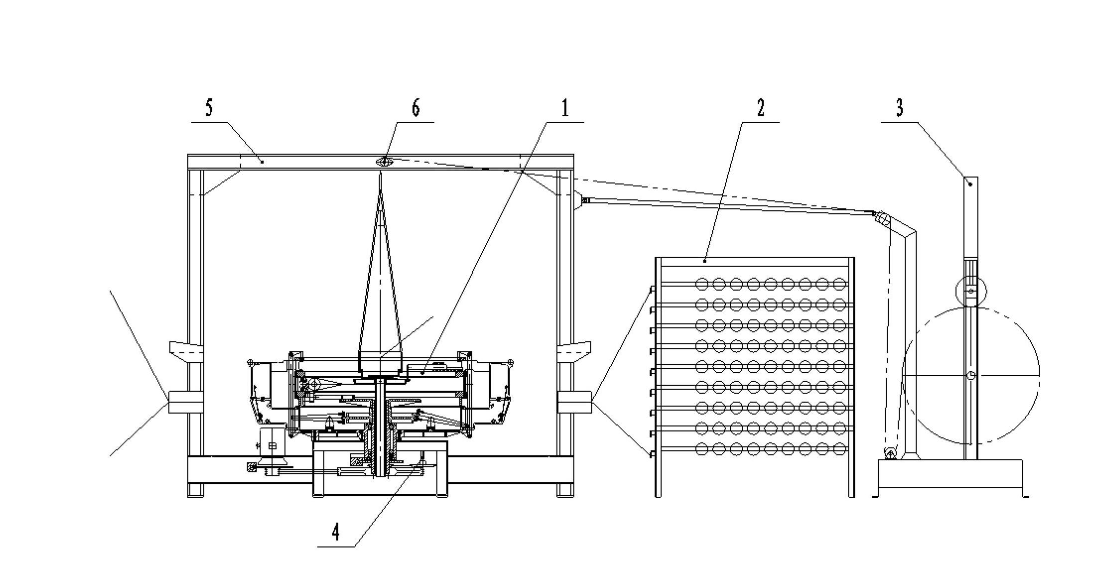
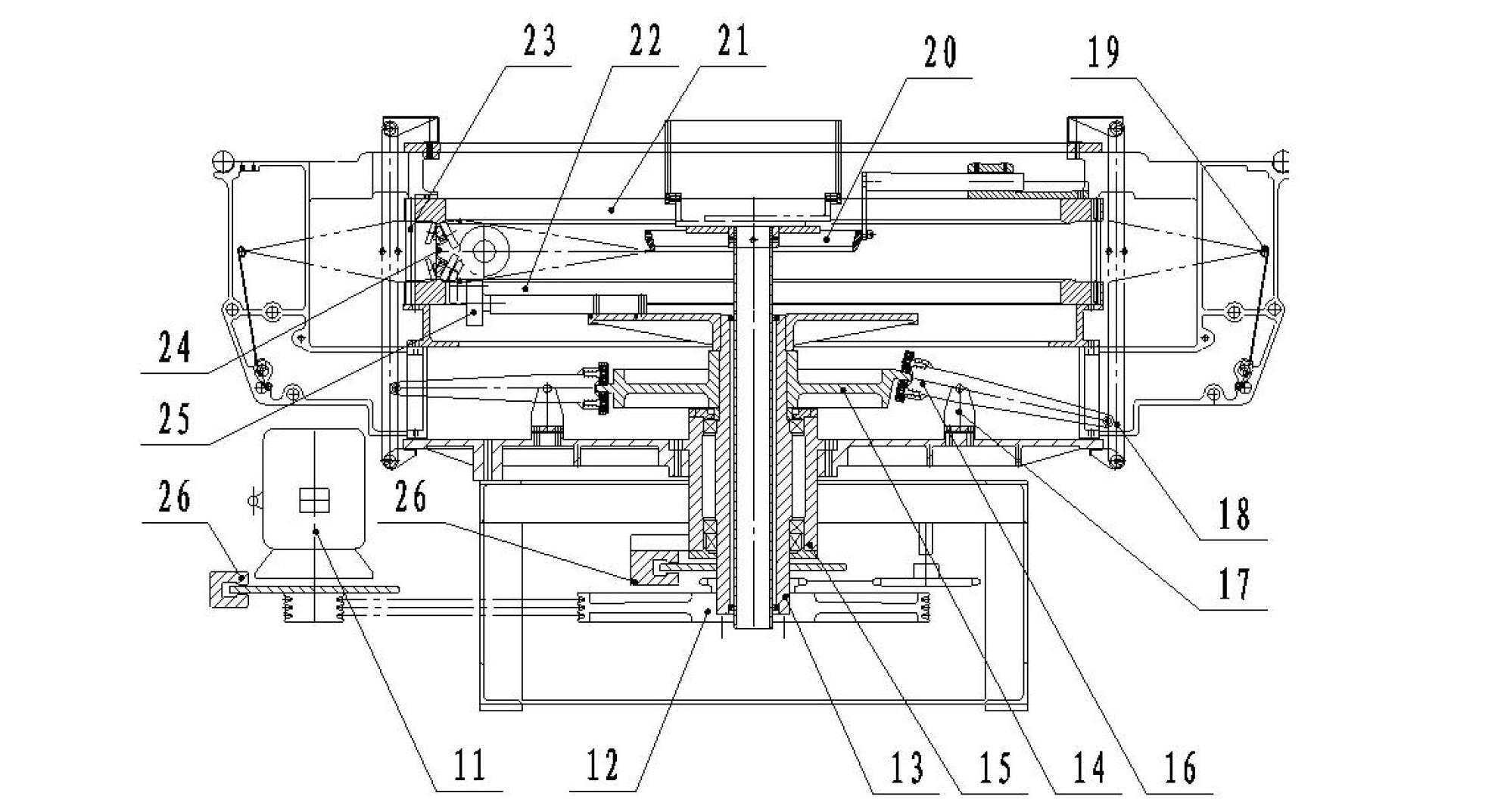

Image

  • Plastic circular weaving machine
  • Plastic circular weaving machine
  • Plastic circular weaving machine

Examples


Embodiment Construction

[0023] The specific implementation of the present invention will be described in further detail below by describing the embodiments with reference to the accompanying drawings, so as to help those skilled in the art have a more complete, accurate and in-depth understanding of the inventive concepts and technical solutions of the present invention.

[0024] Such as figure 1 , figure 2 The structure of the present invention shown is a plastic circular loom, including a main machine 1, a let-off system 2, a winding device 3, and a frame 5; the main machine 1 includes a main motor 11, a transmission system, and a warp opening and delivery mechanism And the weft insertion mechanism, the weft insertion mechanism includes an upper door ring 21, a lower door ring 22, a connecting column 23, a shuttle 24 and a propeller 25; the transmission system includes a pulley 12, a main shaft 13, and a support 14.

[0025] In order to solve the problems existing in the current known technology ...


PUM

PropertyMeasurementUnit
Outer diameteraaaaaaaaaa

Abstract

The invention discloses a plastic circular weaving machine comprising a main machine (1), a let-off system (2), a wrap-up device (3) and a stand (5), wherein the main machine comprises a main motor (11), a transmission system, a warp opening and crossing mechanism and a weft guiding mechanism; the weft guiding mechanism comprises an upper door ring (21), a lower door ring (22), a connection column (23), eight shuttles (24) and eight propellers (25); the transmission system comprises a belt wheel (12), a main shaft (13) and a support (14); and the length of each shuttle (24) is equal to or less than 300mm. According to the technical scheme of the invention, the weaving speed of the plastic circular weaving machine is improved, the power consumption as well as the failure rate and flawed cloth rate of the plastic circular weaving machine is reduced, the service lives of a shuttle wheel and a balance wheel are prolonged, and the structure of the circular weaving machine is simplified.

Description

technical field [0001] The invention belongs to the technical field of plastic braiding machines. More specifically, the present invention relates to a plastic circular loom. Background technique [0002] The plastic circular loom with small cam structure developed in China in recent years has a good power-saving effect and is generally recognized by the market. But there are still deficiencies and room for improvement as described below: [0003] First of all, when weaving woven fabrics with a diameter of less than 800mm, a circular loom with a four-shuttle structure or a plastic circular loom with a small six-shuttle structure is generally used, so its weaving speed and power consumption are subject to certain restrictions; [0004] Secondly, in addition to the winding device, the current plastic circular loom is also equipped with a lifting device. The functions of the two are repeated, which complicates the structure of the equipment, brings inconvenience to the instal...

Claims


Application Information

Patent Timeline
IPC IPC(8): D03D37/00
Inventor 吴劲松
Owner HENGYI PLASTIC EQUIP MFG
Learn More