
Power unit suspension structure for electric vehicle

一种动力单元、电动车辆的技术,应用在电动力装置、下部结构、动力装置等方向,能够解决橡胶套件破损、不能有效地吸收、结构易于与动力单元接触等问题

Active Publication Date: 2012-09-19
SUZUKI MOTOR CORP
View PDF8 Cites 0 Cited by
  • Summary
  • Abstract
  • Description
  • Claims
  • Application Information

AI Technical Summary

Problems solved by technology

[0004] However, in the above-mentioned structure for suspending the power unit of the conventional electric vehicle, the determination of the relative positions of the power unit, the vehicle frame, and the vehicle body, and the determination of the position of the suspension part where the power unit is suspended from the vehicle body, and Insufficient consideration is given to the loads generated in the vertical direction, width direction, and front-rear direction of the vehicle during driving, and the rotational load generated in the vertical direction of the vehicle due to changes in the torque of the motor during driving or deceleration
Therefore, these loads cannot be effectively absorbed, and vibration transmission to the vehicle body cannot be reduced
[0005] In the conventional suspension structure, when a front impact load or a rear impact load is applied to the vehicle, and when these loads cannot be effectively absorbed, the rubber kit in which the power unit is suspended in the suspension portion of the vehicle body may break , or the power unit may be in contact with structures in the front of the vehicle
[0006] In addition, in the conventional suspension structure, when a lateral shock load is applied to the vehicle, the structure in the side of the vehicle is liable to come into contact with the power unit, and the high-voltage cable of the motor and the motor electrode terminal may be broken.

Method used


Image

  • Power unit suspension structure for electric vehicle
  • Power unit suspension structure for electric vehicle
  • Power unit suspension structure for electric vehicle

Examples


Embodiment Construction

[0033] Now, the present invention will be described in detail based on the illustrated embodiments.

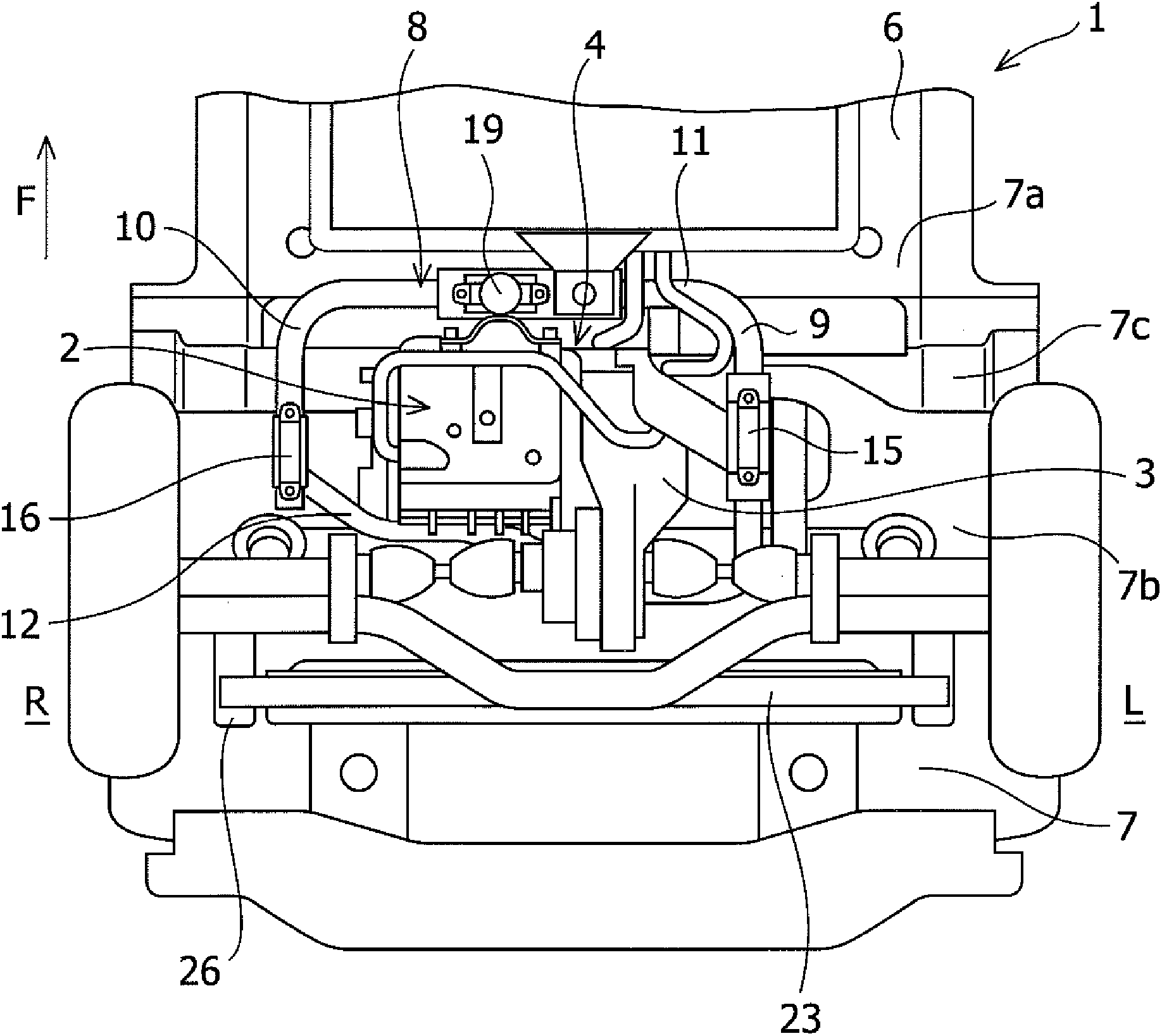
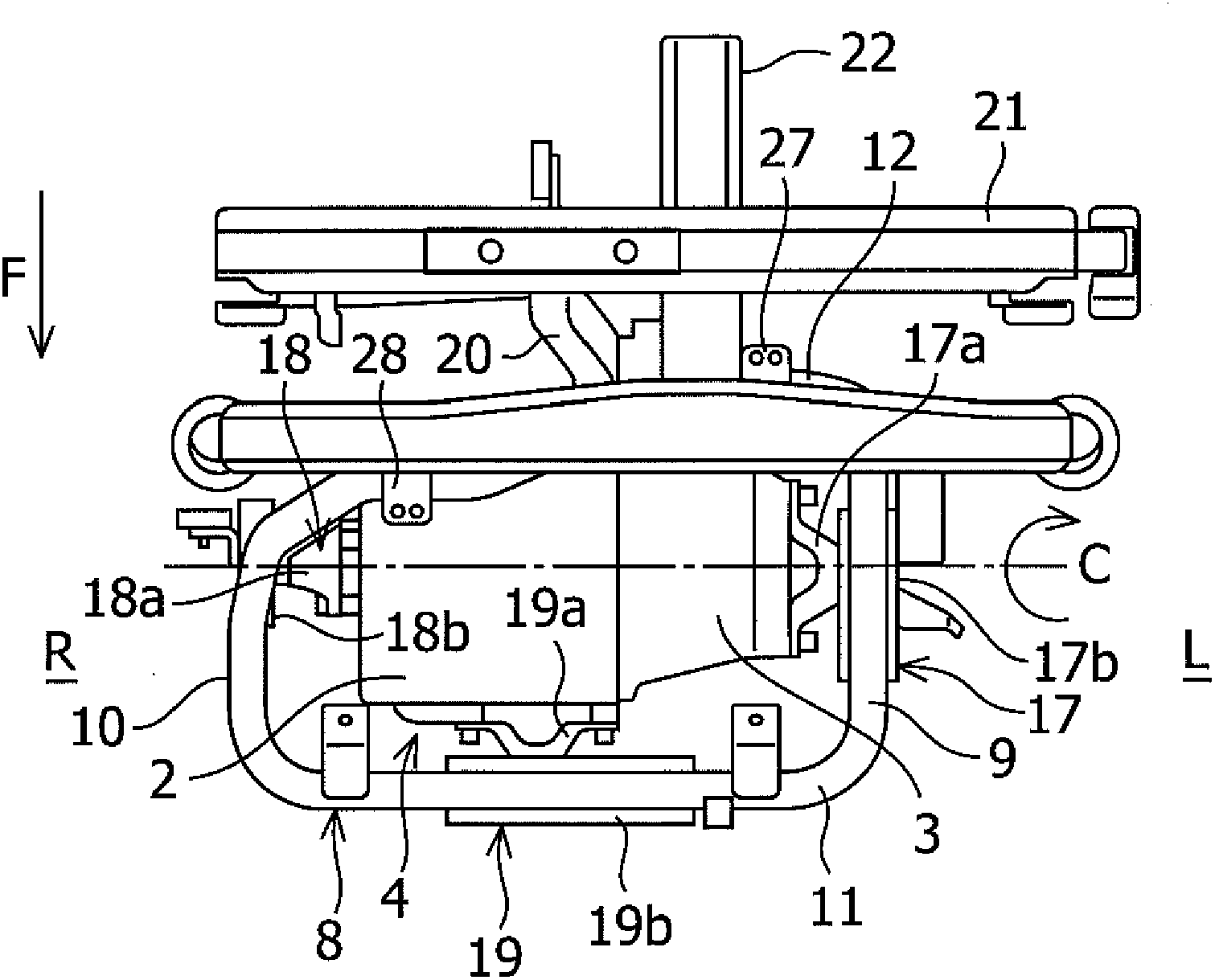
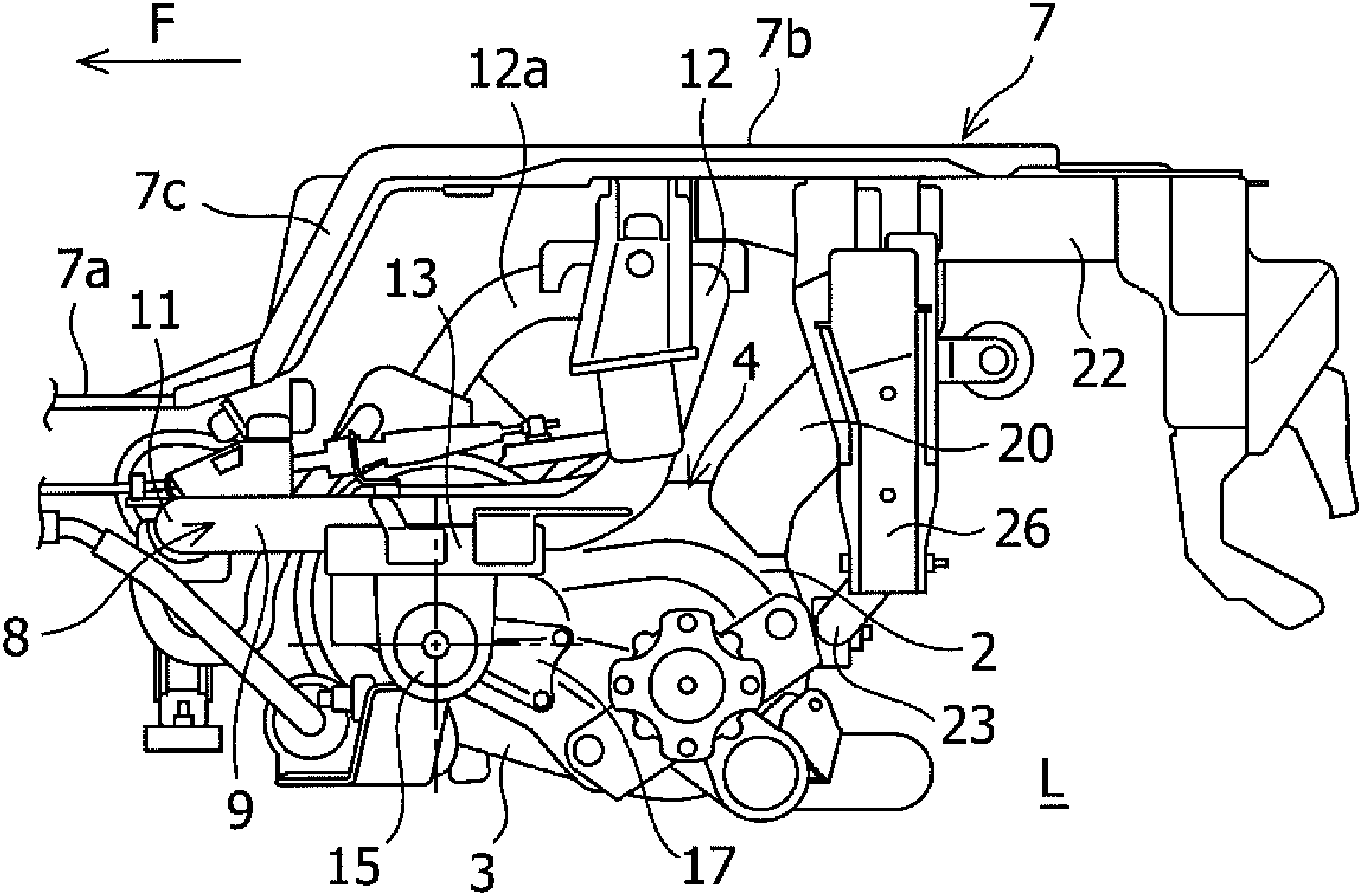
[0034] Figure 1 to Figure 5 A power unit suspension structure for an electric vehicle according to an embodiment of the present invention is shown.

[0035] A vehicle to which the power unit suspension structure according to the embodiment of the present invention is applied is the electric vehicle 1 . The electric vehicle 1 is a rear-drive vehicle such as a commercial vehicle, and travels with the driving force of a motor (electric motor) supplied with electric power. Such as Figures 1 to 5 As shown, a power unit 4 including a motor 2 and a motor reducer 3 is mounted on the rear of the electric vehicle 1 . A shaft C common to the motor 2 and the motor reducer 3 is arranged along the vehicle width direction.

[0036] The power unit 4 is configured such that the motor reducer 3 is connected to the left side of the motor 2 in the vehicle width direction, and the length dir...


PUM


Abstract

The invention relates to a power unit suspension structure for electric vehicle (1). A power unit (4) is mounted in a rear part of a vehicle, a shaft (C) shared by a motor (2) and a motor speed reducer (3) is disposed in a vehicle width direction, and a sub-frame (8) is provided around the power unit (4), a front cross frame (11) is disposed over a front portion of the power unit (4) in a front view of the vehicle and disposed in parallel with the shaft (C) of the motor (2), a rear cross frame (12) is disposed over a side portion of the power unit (4) in a side view of the vehicle, and left and right side portions of the power unit (4) are suspended from a vehicle body via suspension brackets (13) and (14) provided on side frames (9) and (10), circular mount rubbers (15) and (16), and motor-side mount brackets (17) and (18).

Description

technical field [0001] The invention relates to a suspension structure of an electric unit installed at the rear of an electric vehicle. Background technique [0002] In recent years, in consideration of the global environment, along with vehicles having gasoline engines, electric vehicles (EVs) that run using the driving force of a motor (electric motor) have been provided. A power unit including a motor and a motor reducer is installed at the rear of the electric vehicle. [0003] Since such a power unit has a relatively large volume and weight, conventional electric vehicles include a specific structure with high rigidity in the lower part of the vehicle body such as the rear floor to suspend the power unit (for example, see Japanese Patent No. 4508260, Japan Japanese Patent Laid-Open No. 2008-222032, Japanese Patent Laid-Open No. 2008-195259, and Japanese Patent Laid-Open No. 2003-72392). As an example, a frame for suspending the power unit in the lower part of the veh...

Claims


Application Information

Patent Timeline
Patent Type & Authority Applications(China)
IPC IPC(8): B60K1/00
CPCB60K5/1216F16F15/08B60K1/00B62D21/00B62D21/11B60K2001/001
Inventor 立花祐一西川彰浩山根秀一若月淳
Owner SUZUKI MOTOR CORP
Learn More