
Die-cutting machine for flexible material

A die-cutting machine, flexible technology, applied in the direction of metal processing, etc., can solve the problems of low die-cutting accuracy, high labor cost, inaccurate die-cutting position, etc., to reduce purchase and maintenance costs, reduce personnel wage costs, and better Operate the effect of debugging

Inactive Publication Date: 2012-09-19
魏文臣
View PDF7 Cites 1 Cited by
  • Summary
  • Abstract
  • Description
  • Claims
  • Application Information

AI Technical Summary

Problems solved by technology

Although this kind of machine has the characteristics of simple structure and convenient maintenance, its disadvantages are: ①The pressing plate swings around the fixed hinge, and there is a certain inclination between the working surface of the pressing plate and the template surface, so that the die-cutting plate can be cut into the lower part of the cardboard earlier, This will easily lead to the phenomenon that the lower part of the mold plate is under too heavy pressure and the upper part is not completely cut through. In addition, the component force of the die-cutting pressure will also cause the lateral displacement of the cardboard; It is relatively difficult; ③It requires a lot of pressure when working, which leads to high labor intensity and low production efficiency, and the number of working times per minute is 20-30 times; ④There is surface contact between the die cutter and the lower template, which requires Die-cutting can only be carried out if the entire panel meets the die-cutting requirements, and it takes a long time to adjust the machine
Its disadvantages are as follows: ①The die-cutting plate needs to be bent into a curved surface, so the plate making is more troublesome, the cost is relatively high, and there are certain technical difficulties; ②The die-cutting precision is low, and it is not suitable for the window-opening die-cutting with high precision; ③ The blade of the die-cutting knife is located on the arc surface, which has certain restrictions on the thickness of the die-cutting material; ④The die-cutting method of circular press-circle printing and connection is the best die-cutting method for printing and packaging products in large quantities, but because its price is between More than a million, not suitable for small-scale production
However, its disadvantages are: ①Two-person operation, high labor costs; ②Inappropriate cooperation between two people may easily cause safety accidents; ③The round-trip transmission of the die-cutting table is unstable, and the material is prone to displacement with the back-and-forth movement, causing the die-cutting position to be incorrect. Accurate, high-precision window die-cutting has a higher waste rate; ④The function is single, and continuous die-cutting cannot be performed

Method used


Image

  • Die-cutting machine for flexible material
  • Die-cutting machine for flexible material
  • Die-cutting machine for flexible material

Examples


Embodiment Construction

[0026] The present invention will be further described below in conjunction with the accompanying drawings and specific embodiments.

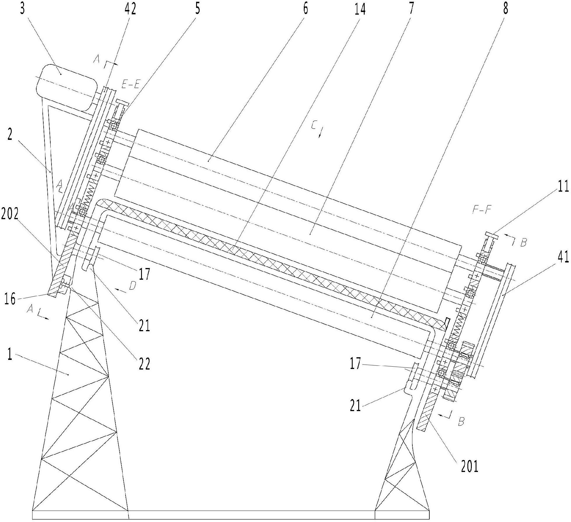
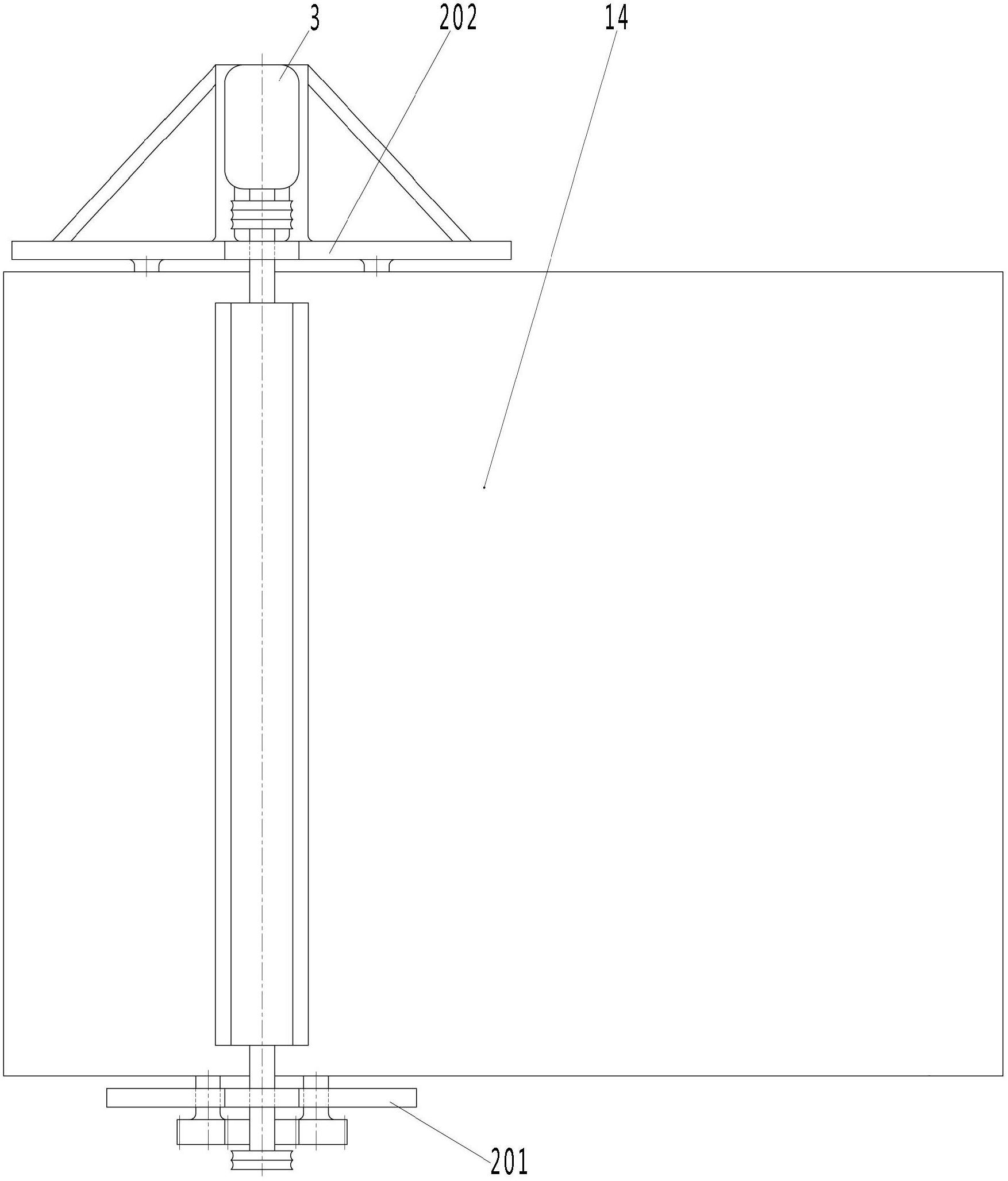
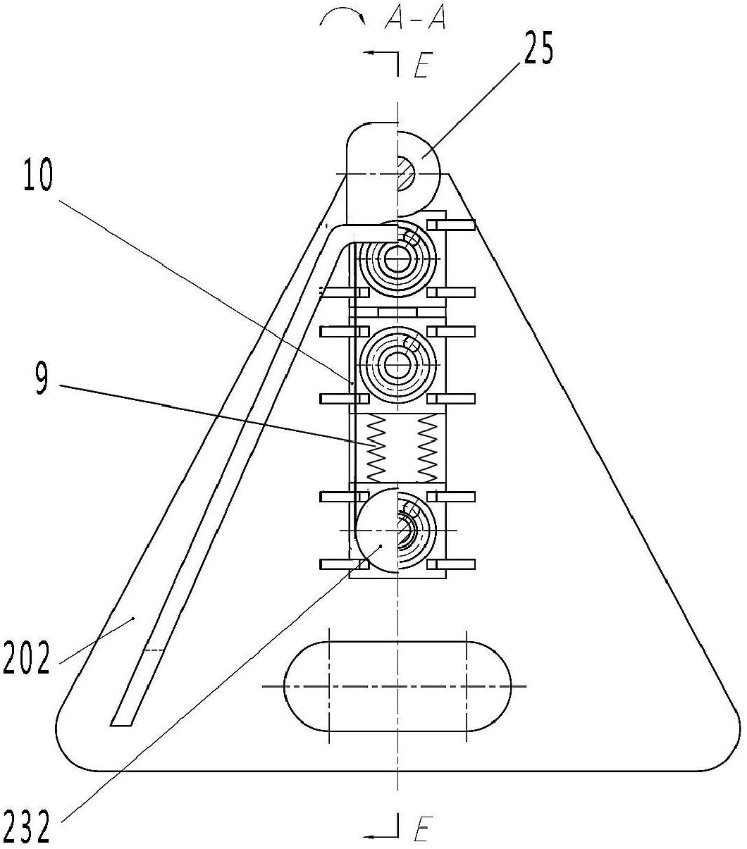
[0027] The present invention includes a frame 1, a motor assembly, a die-cutting platen 14 and a die-cutting assembly.

[0028] For the convenience of description and reference (but not limited thereto), the sliding direction of the die-cutting assembly of the present invention is defined as "left" and "right", and the remaining two sides are defined as "near end" and "far end", wherein the approaching operation The operator's end is called "near end", and the end away from the operator is called "far end".

[0029] Such as figure 1 As shown, the frame 1 is a similar cuboid frame, and the die-cutting table 14 is fixedly installed on the frame 1 . A horizontal guide rail 21 is welded on each side of the inner side of the proximal end and the inner side of the far end of the frame 1 to support the die-cutting assembly.

[0030] Such as figure...


PUM


Abstract

The invention discloses a die-cutting machine for a flexible material and belongs to the field of die-cutting machinery. The die-cutting machine for the flexible material comprises a machine frame and a motor assembly and is characterized by also comprising a die-cutting assembly, wherein the die-cutting assembly comprises a bracket, a pressure roller, a working roller, a supporting roller and a travelling wheel; supporting plates are arranged at two ends of the bracket respectively; two ends of the pressure roller, the two ends of the working roller and the two ends of the supporting roller are movably arranged on the supporting plates; the pressure roller, the working roller and the supporting roller are parallel mutually; supporting components are arranged between two ends of the pressure rollers and two ends of the working rollers; a horizontal guide rail is arranged along the inner side of each of two edges, contacted with the die-cutting assembly, of the machine frame; the direction of the horizontal guide rails is vertical to the axial direction of the working roller; the horizontal guide rails are contacted with the travelling wheel; a motor is connected with the supporting roller through a motor transmission mechanism; the supporting roller is connected with the pressure roller through a homodromous transmission mechanism; the working roller is contacted with the supporting roller; a roller cylinder of the pressure roller is a die-cutting roller cylinder; crease lines and connecting holes are formed on the surface of the die-cutting roller cylinder; and a plurality of die-cutting knife blocks are embedded into the connecting holes. Compared with the prior art, the die-cutting machine for the flexible material has the characteristics of saving labor, improving efficiency and having low scrap rate and high product quality.

Description

【Technical field】 [0001] The parent case of the present invention is the name of the invention: a die-cutting machine, application number 201010609310.5, application date: December 28, 2010. The present invention relates to a die-cutting machine, especially a die-cutting machine suitable for small batches, Die-cutting machine for personalized post-press die-cutting. 【Background technique】 [0002] Die-cutting machine is mainly used for die-cutting (full cut, half-cut), indentation and bronzing of some non-metallic materials, self-adhesive, double-sided tape, electronics, mobile phone rubber pads, etc. important equipment. The working principle of the die-cutting machine is to use the template carved by steel knife, metal mold, steel wire or steel plate, and apply a certain pressure through the embossing plate to cut the printed matter or cardboard into a certain shape. The main parts of the die-cutting machine are the die-cutting platen and the press-cutting mechanism. The...

Claims


Application Information

Patent Timeline
Patent Type & Authority Applications(China)
IPC IPC(8): B26D1/34B26D3/08
Inventor 魏祥国徐冰
Owner 魏文臣
Learn More