Ratchet wrench main body and manufacturing method thereof

A ratchet wrench and body technology, which is applied to the ratchet wrench field, can solve the problems of difficult processing, inability to clean, insufficient lifting force of the lifting member, etc., and achieves the effect of uniform force

Active Publication Date: 2012-09-19
黄平仲
View PDF6 Cites 0 Cited by
  • Summary
  • Abstract
  • Description
  • Claims
  • Application Information

AI Technical Summary

Problems solved by technology

[0003] The first type of known ratchet wrench body 8 is formed in the groove chamber 82 as shown in Figure 9. The drill bit 83 is formed by drilling a drill bit 83 from one end of the ratchet wrench body 8 in a horizontal direction by drilling. A hole 84 will be left at one end of the ratchet wrench body 8. This hole 84 must not only be filled after processing, but also the structure of the ratchet wrench body 8 has been damaged when the hole is formed, so that the ratchet wrench body 8 has The problem of reduced structural strength
[0004] The second type of known ratchet wrench body 9, as shown in Figure 10, has a molded groove chamber 92 in which a drill bit 93 is inserted through the through hole 90 in an oblique manner, and the groove chamber 92 is drilled out. As far as the wrench body 9 is concerned, it is inclined. Although this processing method does not need to leave holes that damage the structure on the ratchet wrench body 8, it is difficult to drill holes in an inclined manner, and when the thickness of the ratchet wrench body 8 is relatively thin The difficulty of drilling is even more obvious, and because the groove chamber 92 that accommodates the top check piece and the elastic piece is inclined, the top check piece is also tilted against the stop block when it is pushed by the elastic piece, and it is easy to make the top check piece Insufficient force of the push piece, causing the problem that the push piece is difficult to be moved
[0005] After the groove chambers 82 and 92 of the above-mentioned two ratchet wrench bodies 8 and 9 are formed in the above-mentioned manner, impurities are likely to remain in the groove chambers 82 and 92 during the processing, and the positions of the groove chambers 82 and 92 are relatively hidden. If there are impurities in the tank chambers 82 and 92 that are installed with elastic parts and top catches, it is easy to cause the blocked catch block to move unsmoothly due to the influence of impurities. At this time, if you want to clean Impurities in the tank chambers 82 and 92 cannot be cleaned

Method used


Image

  • Ratchet wrench main body and manufacturing method thereof
  • Ratchet wrench main body and manufacturing method thereof
  • Ratchet wrench main body and manufacturing method thereof

Examples


Embodiment Construction

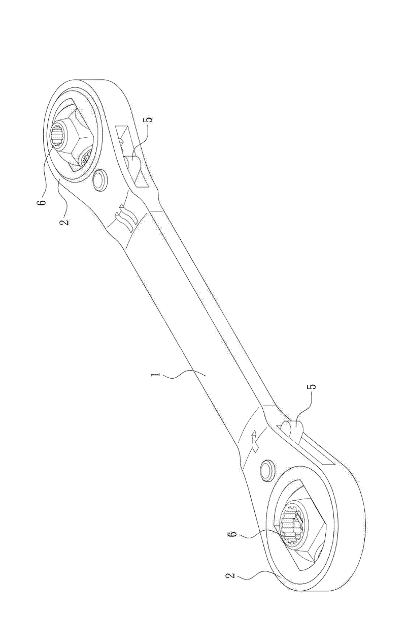
[0033] see Figure 1 to Figure 6 Shown in the figure is the structure of Embodiment 1 selected by the present invention, which is for illustration only, and is not limited by this structure in the patent application.

[0034] The present invention provides a structure of a ratchet wrench body. The structure of the ratchet wrench body can be applied to a ratchet wrench of a one-way drive type, and can also be applied to a ratchet wrench of a two-way switching drive type. Drive type ratchet wrench as an example, that is, figure 1 As shown, the ratchet wrench includes a handle 1, and the two ends of the handle 1 have a head 2 respectively. The ratchet wrench composed of the handle 1 and the two heads 2 is integrally formed and is in a straight shape. In addition, the two heads 2 of this embodiment are respectively provided with a sleeve 6 driven by a two-way pulling block 5 .

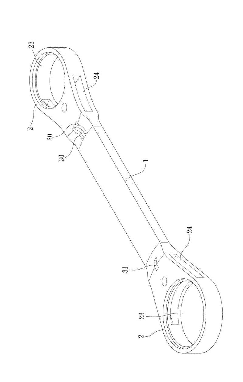
[0035] As shown in Figures 2-3, the two different flat surfaces of the head 2 are respectively a fir...


PUM


Abstract

The invention relates to a ratchet wrench main body and a manufacturing method thereof. The ratchet wrench main body comprises a handle and a head part, wherein a perforated hole accommodating ratchet is sleeved on the head part; the head part is provided with a control chamber accommodated braking block; a fluted chamber is located on one side of a control chamber and is orthogonal with the axial direction of a penetrated hole, so as to accommodate an elastic piece and a jacking piece; the head part is provided with a first surface and a second surface; at least one embedding hole is respectively formed between the first surface and the fluted chamber and between the second surface and the fluted chamber; each embedding hole is formed by removing a slide block during mold casting and mold withdrawing processes; one side of each embedding hole is inserted into the other side but does not pass through the other side; each embedding hole is smaller than the elastic piece and the jacking piece accommodated in the fluted chamber; and the fluted chamber is composed of the total areas occupied by each embedding hole extending into the fluted chamber and intersected adjacent surfaces, thereby forming the ratchet wrench main body.

Description

technical field [0001] The invention relates to a ratchet wrench, in particular to a body structure and a manufacturing method of the ratchet wrench. Background technique [0002] As shown in Figures 9-10, there are two kinds of known ratchet wrench bodies 8, 9, which respectively have a perforation 80, 90 for accommodating a ratchet at one end, and a perforation 80, 90 adjacent to this perforation 80, 90 for accommodating The accommodating chamber 81, 91 of the trigger block, and a groove chamber 82, 92 for accommodating the top catch member and the elastic member is deepened inside the accommodating chamber 81, 91. [0003] The first type of known ratchet wrench body 8 is formed in the groove chamber 82 as shown in Figure 9. The drill bit 83 is formed by drilling a drill bit 83 from one end of the ratchet wrench body 8 in a horizontal direction by drilling. A hole 84 will be left at one end of the ratchet wrench body 8. This hole 84 must not only be filled after processin...

Claims


Application Information

Patent Timeline
IPC IPC(8): B25B13/46B22C9/22
Inventor 黄平仲
Owner 黄平仲
Why Eureka
Try Eureka