Spinal surgery tool

A surgical tool and spine technology, applied in the field of surgical tools, can solve the problems of positioning angle limitation, affecting the path of prosthesis introduction, and inapplicable fusion device implantation, etc.

Inactive Publication Date: 2012-09-19
INTAI TECH CORP
View PDF9 Cites 7 Cited by
  • Summary
  • Abstract
  • Description
  • Claims
  • Application Information

AI Technical Summary

Problems solved by technology

Ratchet-based fit also has limitations in positioning angles, which also affects the prosthetic insertion path
In addition, based on the combination of the prosthesis and the device, this device is only suitable for the introduction and export of the prosthesis, not for the implantation of the fusion device

Method used


Image

  • Spinal surgery tool
  • Spinal surgery tool
  • Spinal surgery tool

Examples


Embodiment Construction

[0063] In order to illustrate the central idea of ​​the present invention expressed in the column of the above-mentioned summary of the invention, it is expressed in specific embodiments. Various objects in the embodiments are drawn according to proportions, sizes, deformations or displacements suitable for illustration, rather than drawn according to the proportions of actual components, as stated in advance. And in the following description, similar components are denoted by the same numerals.

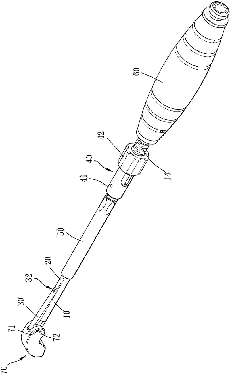
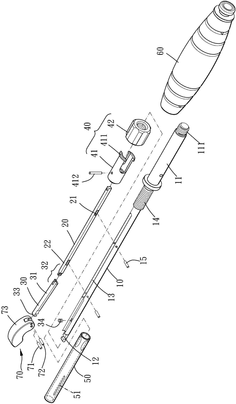
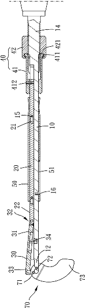
[0064] see figure 1 , figure 2 with image 3 , the surgical tool for guiding the intervertebral device of the present invention includes: a fixed rod 10 , a sliding rod 20 , a joystick 30 , a control group 40 , a cannula 50 , and a handle 60 . The combination and positional relationship of each component are described in detail as follows:

[0065] The first end 11 of the fixing rod 10 is inserted into the handle 60, and the two are combined and fixed by threads 111. The second...


PUM


Abstract

The invention provides a spinal surgery tool which comprises a fixing rod, a sliding rod, an operating rod, a spring, a controlling group and a sleeve pipe. One end of the fixing rod is an operating end of an intervertebral device; the fixing rod is provided with a linear moving space; the sliding rod moves in a reciprocating mode in the linear moving space; the operating rod is arranged in the linear moving space, a first end of the operating rod is connected with an end portion of the sliding rod through a rotating pivot, and a second end of the operating rod is an operating end of the intervertebral device; the operating rod is controlled by the sliding rod and can move in a reciprocating mode in the linear moving space; the spring is arranged in the linear moving space, and an elasticity end of the spring acts on the operating rod; the controlling group is arranged on a rod body of the fixing rod between a handle and the sliding rod in a linear moving mode and connected with the sliding rod; and the sleeve pipe is confined outside a combined structure of the fixing rod and the sliding rod and can move in a reciprocating mode along the fixing rod so as to restrain or be separated from the operating rod. The spinal surgery tool has the advantage of being capable of guiding the intervertebral device to enter an intervertebral disk accurately and stably.

Description

technical field [0001] The invention relates to a surgical tool, especially a surgical tool which can accurately and stably guide an intervertebral device into an intervertebral disc. Background technique [0002] Human intervertebral disc degeneration is one of the common degenerative diseases in middle-aged and elderly people. Spinal interbody fusion can improve this type of disease. It is to place a fusion device between the degenerated intervertebral discs to open the vertebral bodies, so as to reduce the compression on the nerve roots, reduce pain and fuse the intervertebral joints. [0003] Intervertebral fusion surgery is generally divided into three types: anterior, posterior, and poster-lateral approaches, and the types of intervertebral fusion devices used with them are also different. [0004] The surgical method of adopting the side-to-posterior approach has been initially disclosed in patent publications such as U.S. No. 2007 / 0093850 (hereinafter referred to as...

Claims


Application Information

Patent Timeline
Patent Type & Authority Applications(China)
IPC IPC(8): A61F2/46A61B17/90
CPCA61F2/4611A61F2/44A61F2002/30001
Inventor 蔡永芳刘崇震廖永富
Owner INTAI TECH CORP
Why Eureka
Try Eureka