Slider for slide fastener with automatic stopper

An automatic braking and zipper technology, applied in the field of zipper sliders, can solve problems such as complex slider structures

Active Publication Date: 2009-04-08
YKK CORP
View PDF5 Cites 0 Cited by
  • Summary
  • Abstract
  • Description
  • Claims
  • Application Information

AI Technical Summary

Problems solved by technology

Then, the structure of the slider is complicated as mentioned above, and there is a limitation on the accurate installation of the pull tab to the slider assembly product, so, it has been required that the installation work of the pull tab is easy

Method used


Image

  • Slider for slide fastener with automatic stopper
  • Slider for slide fastener with automatic stopper
  • Slider for slide fastener with automatic stopper

Examples


Embodiment Construction

[0073] DETAILED DESCRIPTION OF THE PREFERRED EMBODIMENTS Preferred embodiments of the present invention will be described below with reference to the accompanying drawings.

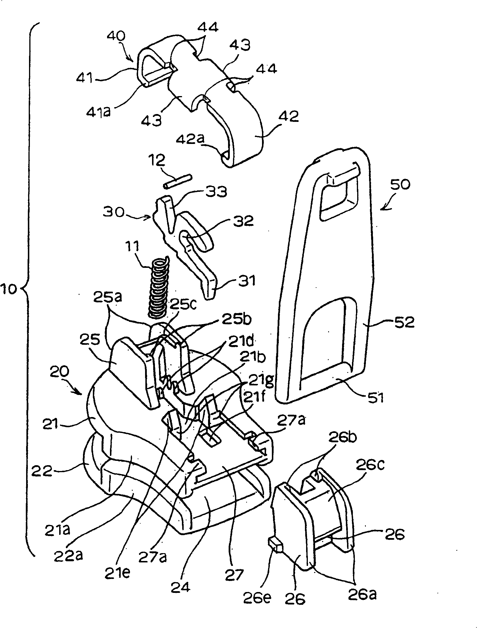
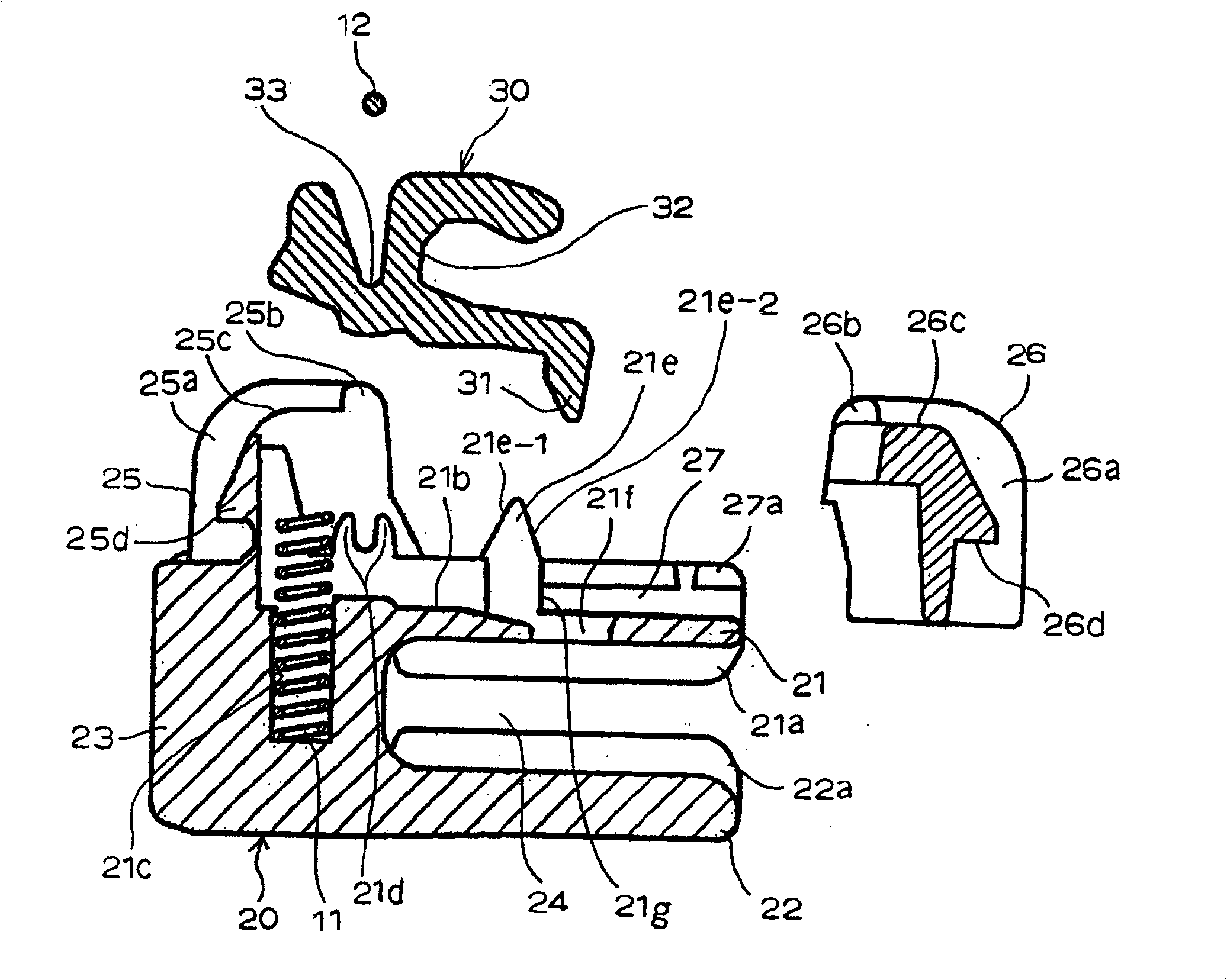
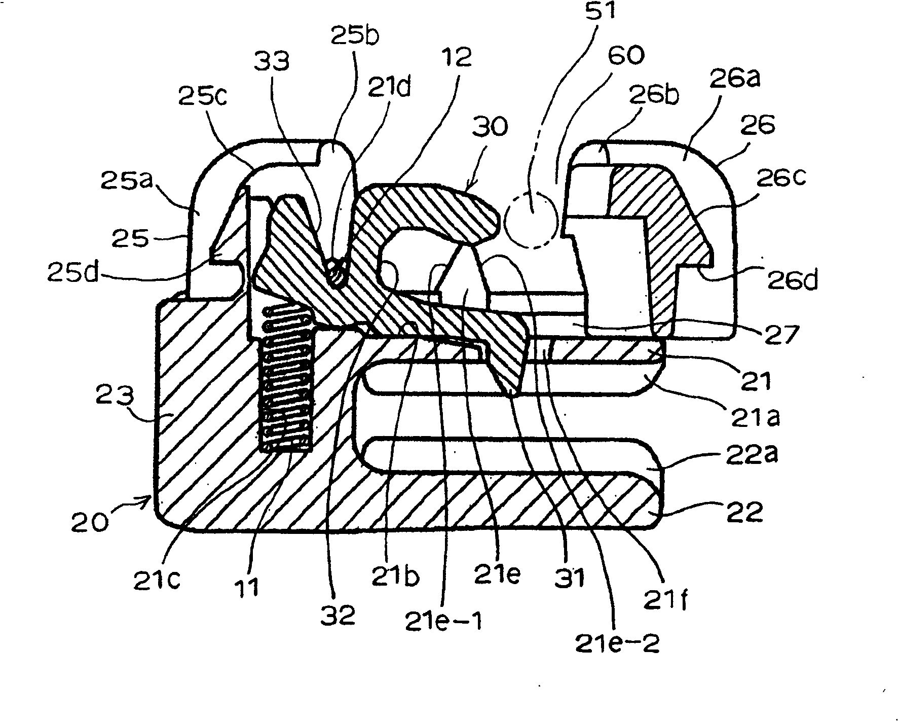
[0074] Figures 1 to 9 A representative first embodiment of the present invention is shown. figure 1 is a perspective view showing a disassembled state of parts constituting a slider for a zipper with an automatic stopper. Figures 2 to 8 is a longitudinal sectional view of the main part showing the assembly steps of the same slider, while Figure 9 is a perspective view of the same slider. In this embodiment, the shoulder side of the slider ( figure 1 The left side of the slider) is called the front, and the rear opening side of the slider ( figure 1 middle right) is called the posterior.

[0075] (first embodiment)

[0076] refer to figure 1 , the slider 10 for a slide fastener with an automatic brake includes a slider body 20, a front mounting column 25, a rear mounting column 26, a pawl bod...


PUM


Abstract

This invention relates to a slider for a slide fastener with an automatic stopper comprising front and rear mounting pillars of a slider body and a pawl body open to the rear mounting pillar and having a concave portion for accommodating a shaft portion of a pull wherein a gap portion allowing the shaft portion to pass through is formed in the concave portion by disposing the rear mounting pillar in a fitting guide groove in the slider body slidably in back and forth directions, and the shaft portion is prevented from slipping out of the concave portion through the gap portion when a pull holding body for covering the slider body is engaged with the front and rear mounting pillars, whereby simplifying a slider body's structure, an attachment structure of the pull and manufacturing procedure, and reducing a manufacturing cost while securing a stable / excellent automatic stopper function.

Description

technical field [0001] The present invention relates to a slider for a slide fastener with an automatic braking function, more particularly, to a slider for a slide fastener with an automatic brake, which can simplify the structure of the slider body and make the pull tab It is easy to install on the slider body. Background technique [0002] Conventionally, a slider for a zipper with an automatic braking function is often used, in which by operating the pull tab of the slider body, which joins / separates the element rows of the zipper element chain, a detent pawl The brake pawl of the body is engaged with a part of the element row of the zipper chain so as to stop the movement of the slider body (for example, see Japanese Utility Model Publication No. 4-32974). [0003] In the slider 100 described in Japanese Utility Model Publication No. 4-32974, as Figure 17 and 18 As shown, a downward concave pull tab fixing body 102 is firmly fixed to the slider body 101 from the shou...

Claims


Application Information

Patent Timeline
Patent Type & Authority Patents(China)
IPC IPC(8): A44B19/30A44B19/26
CPCA44B19/308Y10T24/2577Y10T24/2568Y10T24/257Y10T24/2571A44B19/26
Inventor 岩濑裕一槻庆一
Owner YKK CORP
Why Eureka
Try Eureka