
Medical mechanical arm tail end device

A terminal device and robotic arm technology, which is applied in the field of medical robotic arm terminal devices, can solve the problems of patients' surgical injuries, difficulty in obtaining coordinate positioning in image space and patient space, and lack of doctor's sense of presence.

Inactive Publication Date: 2012-09-19
SOUTH CHINA UNIV OF TECH
View PDF10 Cites 14 Cited by
  • Summary
  • Abstract
  • Description
  • Claims
  • Application Information

AI Technical Summary

Problems solved by technology

[0007] 5) In addition, the existing stereotaxic technology is difficult to apply to the operation of other parts of the human body, the main reason is that the position of the soft tissue in other parts of the human body is not fixed relative to the surrounding bone tissue, making it difficult to achieve a consistent image space and patient space Coordinate positioning
However, this invention cannot automatically evacuate the puncture needle from the robot. Due to the spatial interference of the robot, the subsequent manual puncture operation is very difficult. If the machine is directly used to replace the subsequent manual puncture operation, abnormal situations will occur. This is because surgery The process is completely forced by the machine, lacking the doctor's sense of presence, causing serious surgical injuries and risks to the patient

Method used


Image

  • Medical mechanical arm tail end device
  • Medical mechanical arm tail end device
  • Medical mechanical arm tail end device

Examples


Embodiment

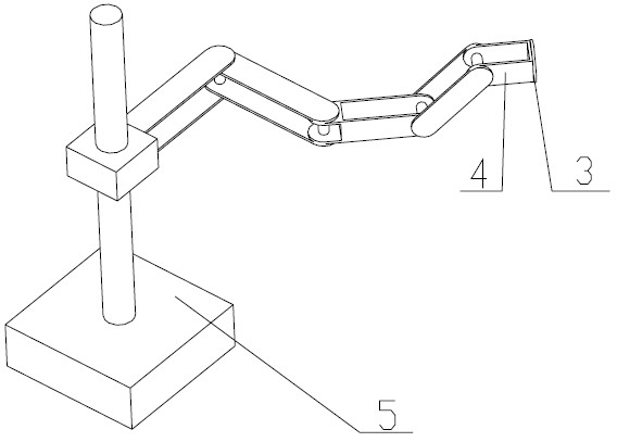
[0037] As an end effector of a medical robot arm, the present invention needs to be attached to a robot arm for automatic positioning and attitude determination.

[0038] Such as figure 1 As shown, the mechanical arm 5 can enable the loading and unloading guide mechanism 1 in the present invention to realize the orientation of the desired position / posture, which requires a certain number of degrees of freedom. Since the degree of freedom of needle rotation around the axis is not required, only 5 degrees of freedom are needed to complete the basic task, of which 3 degrees of freedom are used for spatial positioning, and the other 2 are used for attitude adjustment. However, in actual situations, redundant 5 degrees of freedom are redundantly controlled to avoid abnormal situations such as interference, joint limits, and singular points.

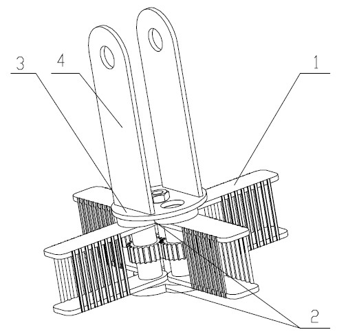
[0039] Such as figure 2 As shown, the terminal device of the medical mechanical arm includes a loading and unloading guide mechanism 1 (h...


PUM


Abstract

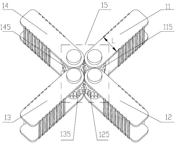
The invention discloses a medical mechanical arm tail end device which comprises a loading and unloading guide mechanism, an assembly and a connecting plate, wherein the loading and unloading guide mechanism is used for loading and unloading a needle-shaped medical appliance; the assembly is used for installing the loading and unloading guide mechanism; the connecting plate is used for fixing the assembly on a connecting rod at the tail end of a mechanical arm; the loading and unloading guide mechanism comprises four fixture bodies with the same structure and a loading and unloading transmission mechanism for driving the four same fixture bodies to rotate; and each fixture body comprises a rotating shaft, an upper clamping plate, a lower clamping plate and a plurality of guide sleeves. Under the action of the transmission mechanism, a closed hole is formed by the corresponding guide sleeves of the two adjacent fixture bodies so as to guide an actuator; and after the guidance is completed, the transmission mechanism is reversely driven to separate the fixture bodies. The medical mechanical arm tail end device is mainly used for automatically loading, unloading and guiding an ablation needle in a tumor ablation operation, ensures that a doctor has a sufficiently large operating space after the ablation needle is positioned / subjected to posture positioning, and has high automation degree, high accuracy, simpleness for operation and strong coordinability between people and a machine.

Description

technical field [0001] The invention relates to a terminal device of a mechanical arm, in particular to a terminal device of a medical mechanical arm for assisting automatic loading, unloading and guiding of needle-shaped medical instruments in tumor ablation operations. Background technique [0002] When a lesion occurs inside the human body, and the patient's physical condition does not allow surgical resection, sometimes it is necessary to use puncture to biopsy or treat the lesion (radiofrequency ablation, chemical ablation, microblog ablation). Usually by means of instruments such as CT / MRI scanning devices to measure the orientation of the lesion and the skin location point and the depth of the puncture needle (ablation needle), first measure the position of the lesion on the cross-section of the human body, and select the best Needle insertion position and needle insertion angle, using the three-dimensional configuration of the needle insertion level, needle insertion...

Claims


Application Information

Patent Timeline
IPC IPC(8): A61B18/00A61B10/02
CPCA61B19/2203A61B19/26A61B2018/00577A61B19/00A61B17/00A61B2018/1425A61B34/30A61B90/50
Inventor 张勤徐策
Owner SOUTH CHINA UNIV OF TECH
Learn More