
Cyclone separating device for reducing anticyclone

A technology of cyclone separation device and cyclone separator, which is applied in suction filters and other directions, can solve the problems of reducing dust separation efficiency, difficulty in dust collection, and reducing air flow speed, and achieve the effect of ensuring suction power, fast air flow speed and reducing leakage.

Inactive Publication Date: 2012-09-19
LG ELECTRONICS (TIANJIN) APPLIANCES CO LTD
View PDF6 Cites 0 Cited by
  • Summary
  • Abstract
  • Description
  • Claims
  • Application Information

AI Technical Summary

Problems solved by technology

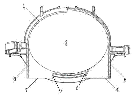
[0010] The air inlet and the dust outlet of the existing cyclone separator mostly adopt such as figure 2 The form shown is that it is tangent to the shape of the cyclone separator and vertically downwards. When the air with dust enters the elliptical cyclone separator from the air inlet and rotates to separate the dust, the vertical airflow through the air inlet will have an angle. Larger direction changes will reduce the airflow speed and at the same time produce reverse cyclones, which will cause greater Reynolds stress and reduce dust separation efficiency
Moreover, the dust discharge port is mostly sealed at the contact part in the structure where the dust collection box and the cyclone separator are separated. Such a dust discharge port has a limited impact on the dust collection efficiency, especially in the dust discharge port of the cyclone separator. There is also a large amount of dust gas Backflow phenomenon, the collection of dust will cause certain difficulties because of such a structure

Method used


Image

  • Cyclone separating device for reducing anticyclone
  • Cyclone separating device for reducing anticyclone
  • Cyclone separating device for reducing anticyclone

Examples


Embodiment Construction

[0030] The present invention will be described in detail below with reference to the drawings and embodiments. In the present invention, the same components as in the prior art use the same symbols.

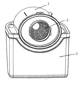
[0031] The cyclone separation device of the present invention is arranged in the dust collection device, and the dust collection device includes a dust collection bucket, a cyclone separator, and a filter horizontally installed inside the barrel of the cyclone separator. The back end of the cyclone is closed and the front end is open. An air inlet is formed on the front wall of the barrel of the cyclone separator, and the rear end of the lower barrel wall of the cyclone barrel is provided with a dust outlet; the front end of the filter forms a dust outlet. A cylinder on the same center line as the filter is arranged on the inner side of the closed end of the cyclone separator.

[0032] When the suction fan of the vacuum cleaner is working, the dust near the suction head and the air ...


PUM


Abstract

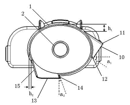
The invention discloses a cyclone separating device for reducing anticyclone. The cyclone separating device comprises a cyclone separator and a filter horizontally installed in a barrel body of the cyclone separator, wherein an air inlet is arranged at one side of the cyclone separator; the outer wall of the air inlet is formed along a peripheral tangent line of the barrel body of the cyclone separator; an included angle with a certain degree is formed between the outer wall of the air inlet and a parallel line of a peripheral tangent line at the minimum diameter of the cyclone separator; and the inner wall of the air inlet is formed in parallel to the outer wall of the air inlet. According to the cyclone separating device for reducing the anticyclone, an included angle with a certain degree is formed between the outer wall of the air inlet and the parallel line of the peripheral tangent line at the minimum diameter of the cyclone separator, and the outer wall of the air inlet is formed along the peripheral tangent line of the barrel body of the cyclone separator. When air inlet direction is changed for air suction in the tangent line with larger eccentricity, the anticyclone is reduced and resistance of the anticyclone to the air suction is reduced, so that the efficiency of the cyclone separator is improved.

Description

Technical field [0001] The invention belongs to the field of vacuum cleaners, and particularly relates to a cyclone separation device capable of reducing anticyclone. Background technique [0002] Dust collection is a kind of clean and sanitary appliance used to remove dust from floors, carpets, walls, furniture, clothes and various crevices. Generally speaking, a vacuum cleaner mainly includes a suction device and a suction pipe. The suction device mainly formed by a motor and a fan is set in the body of the vacuum cleaner. The suction pipe includes a suction head, a dust suction tube and a dust hose. The head has a downwardly opening suction port and communicates with the air inlet of the fan in the vacuum cleaner body through a dust suction tube and a dust hose. [0003] When the vacuum cleaner is running, the motor drives the impeller of the fan to rotate at a high speed, expelling the air inside the vacuum cleaner, forming an instantaneous vacuum inside the vacuum cleaner, an...

Claims


Application Information

Patent Timeline
IPC IPC(8): A47L9/16
Inventor 陈永恒
Owner LG ELECTRONICS (TIANJIN) APPLIANCES CO LTD
Learn More