Valve prosthesis
A valve prosthesis and prosthesis technology, applied in prosthesis, heart valve, medical science, etc.
- Summary
- Abstract
- Description
- Claims
- Application Information
AI Technical Summary
Problems solved by technology
Method used
Image

Examples
Embodiment I
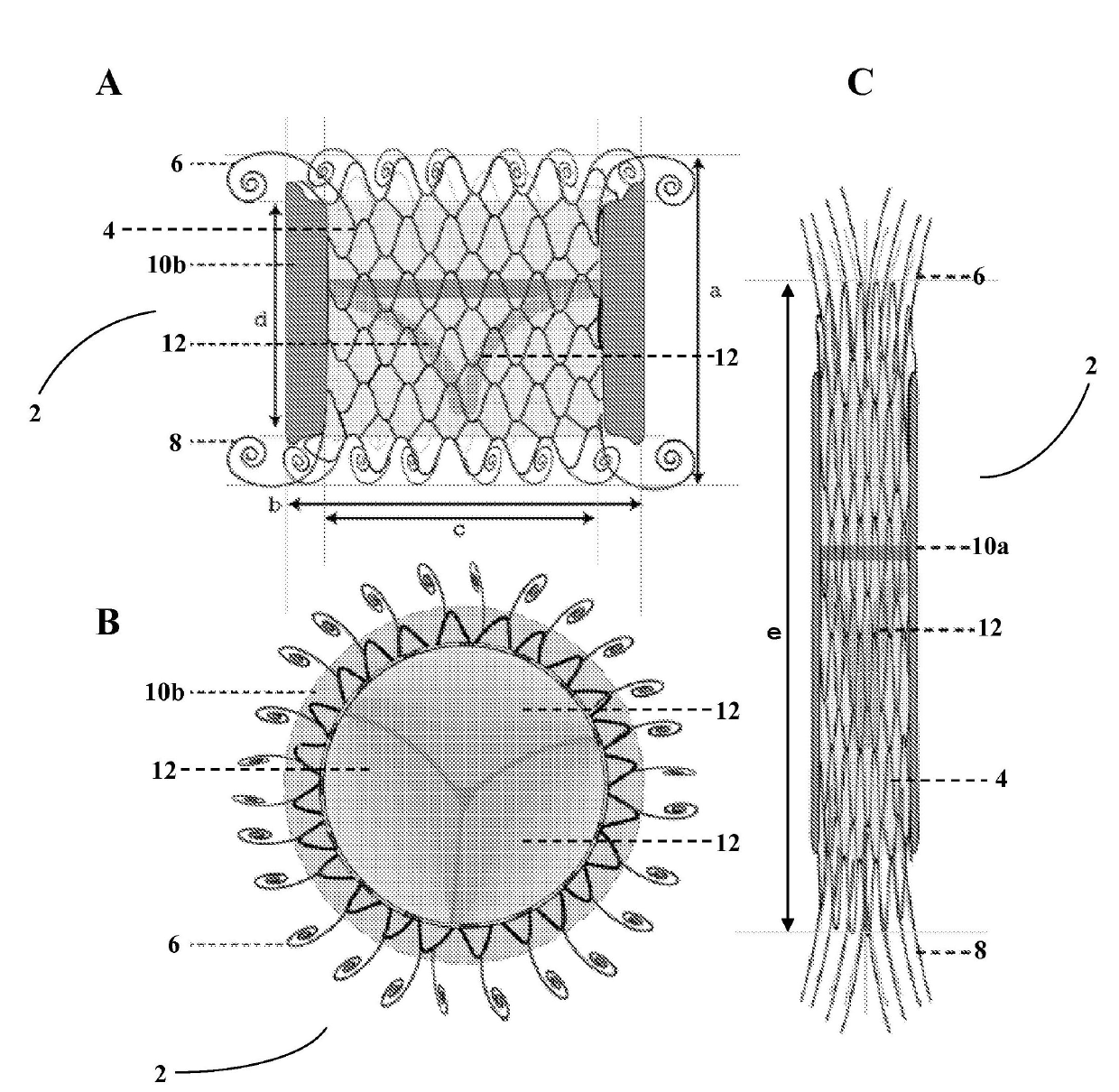
[0031] The following disclosure relates to a first general embodiment of the present disclosure, which relates to the valve prosthesis of the present invention and a method for replacing a damaged or diseased valve.
[0032] In one aspect, a valve prosthesis is provided, which includes: a self-expanding stent including an outer surface, an inner surface, a middle region, an upper anchoring flange, and a lower anchoring flange, wherein the stent has an unexpanded state and Expanded state; a cuff, the cuff includes an absorbent material disposed at least partially circumferentially around the outer surface of the stent, wherein the absorbent material expands by absorbing fluid to make the prosthesis substantially attached to the implantation site, and wherein the anchoring is The delay is sufficient time to allow the prosthesis to be positioned at the implantation site; and a valve that includes at least two leaflets fixedly attached to the inner surface of the stent. In a preferre...
Embodiment II
[0055] The following description relates to the second general embodiment of the present disclosure, which relates to the valve prosthesis of the present invention; a method for replacing a damaged or diseased valve; a system for delivering a valve prosthesis; a kit; and for delivery Valve prosthesis method.
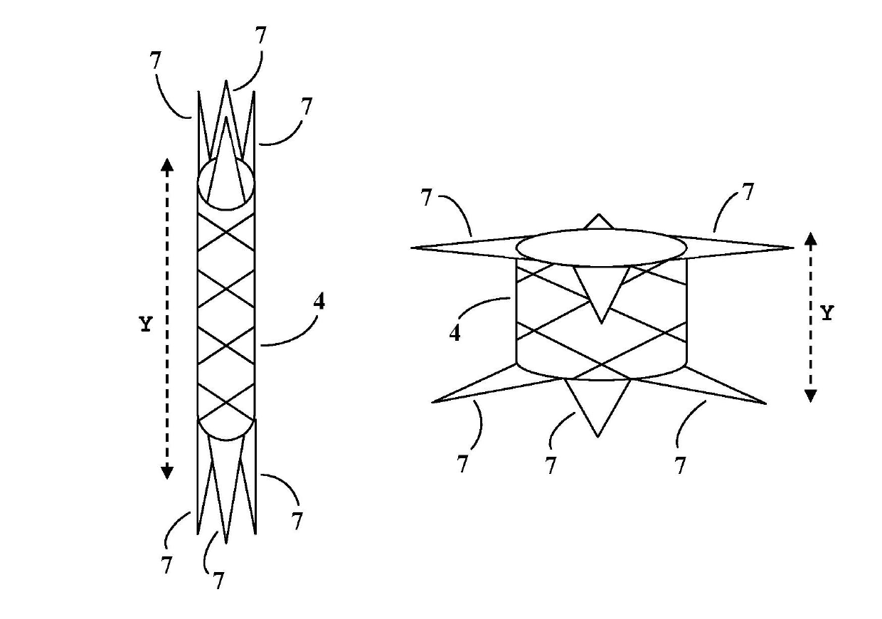
[0056] In one aspect, a valve prosthesis is provided, which includes: an at least partially self-expanding stent, the stent including a wire skeleton defining an outer surface and an inner surface, and upper and lower anchoring flanges inserted into the middle region, the stent having a An expanded state and an expanded state, and the lower anchoring flange has at least one geometric size larger than the corresponding size of the upper anchoring flange; and a valve including at least one leaflet fixedly attached to the inner surface of the stent.
[0057] The stent may be configured to be at least partially self-expanding. For example, the stent may be capable of self-expand...
example 1
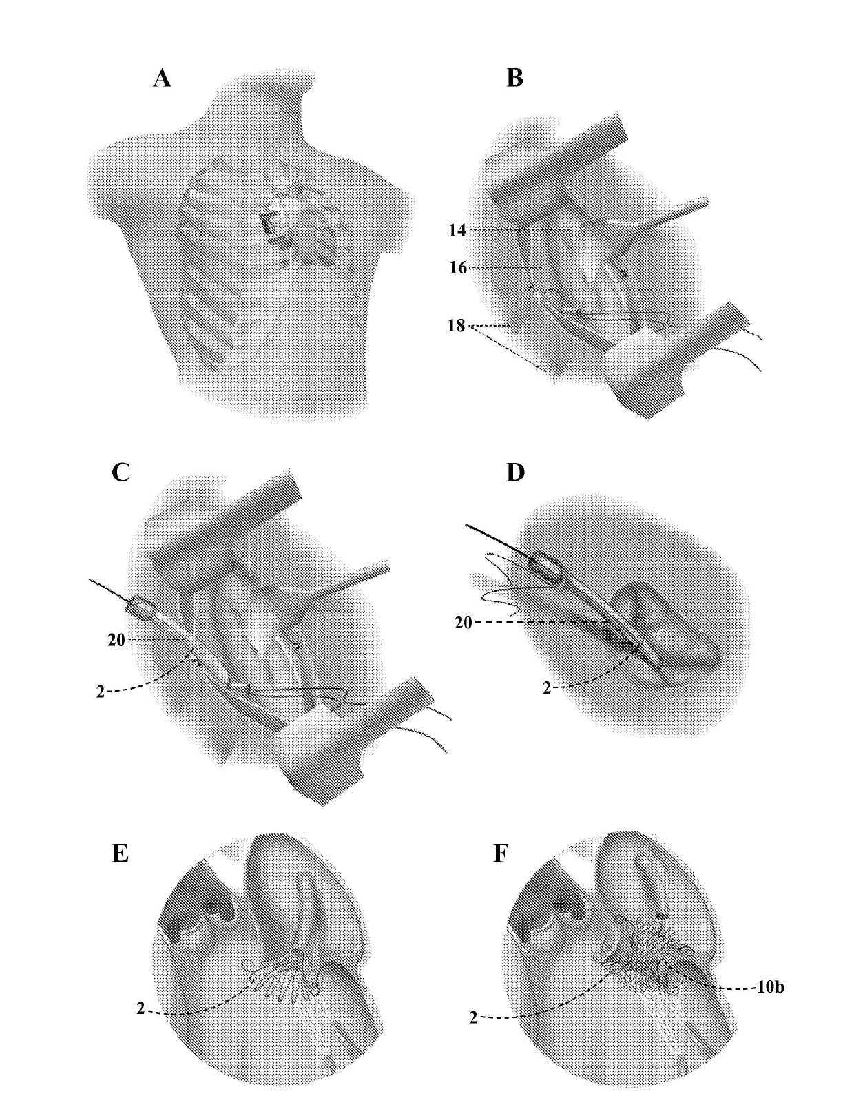
[0116] Example 1-Percutaneous implantation via transfemoral method
[0117] Using the system for delivering valve prostheses disclosed in the present invention and the valve prostheses according to the present disclosure, exemplary delivery and implantation procedures can be performed as follows.
[0118] First, enter the femoral vein (right or left) and use the Seldinger technique to insert the vascular sheath. A standard transseptal technique is used to traverse the atrial septum, and a balloon dilatation atrial septostomy (10-15mm angioplasty balloon) creates / enlarges the atrial hole.
[0119] The super-hard guide wire is carefully shaped and then positioned in the left ventricle through the newly created atrial hole. The femoral vein entry site is made larger or "dilated up" using a continuously enlarged vasodilator, where the vasodilator is appropriately sized to match the diameter of the delivery system.
[0120] The valve prosthesis is compressed and positioned on the docking ...
PUM
| Property | Measurement | Unit |
|---|---|---|
| thickness | aaaaa | aaaaa |
| diameter | aaaaa | aaaaa |
| diameter | aaaaa | aaaaa |
Abstract
Description
Claims
Application Information
 - Generate Ideas
- Intellectual Property
- Life Sciences
- Materials
- Tech Scout
- Unparalleled Data Quality
- Higher Quality Content
- 60% Fewer Hallucinations
Browse by: Latest US Patents, China's latest patents, Technical Efficacy Thesaurus, Application Domain, Technology Topic, Popular Technical Reports.
© 2025 PatSnap. All rights reserved.Legal|Privacy policy|Modern Slavery Act Transparency Statement|Sitemap|About US| Contact US: help@patsnap.com