
User interface based operation triggering method and operation triggering device and terminal equipment

A user interface and trigger device technology, applied in the computer field, can solve problems such as insufficient physical space, prone to misoperation, and inconvenient operation, and achieve the effects of reducing control costs, reducing moving distances, and enhancing interactivity

Active Publication Date: 2012-09-12
BEIJING QIHOO TECH CO LTD
View PDF5 Cites 36 Cited by
  • Summary
  • Abstract
  • Description
  • Claims
  • Application Information

AI Technical Summary

Problems solved by technology

[0004] When using a touch screen to operate the user interface, the user's finger is usually in the center of the user interface due to operations such as turning the screen up and down, and the operation trigger area such as the interaction button is usually designed around the user interface. Moving from the center position to the edge, especially when performing a moving operation with a long stroke, the operation is inconvenient and prone to misoperation
[0005] When using a mouse to operate the user interface on an ordinary screen, the operation trigger areas such as interactive icons are usually designed to be scattered, and the ordinary screen is often large. When using the mouse to perform mobile operations, the travel distance is often very long, and it is easy to misuse. And the operation is very inconvenient, which is especially obvious when the physical space for mouse operation is not enough. It is even necessary to lift the mouse several times and move it back to the starting position to continue moving.

Method used


Image

  • User interface based operation triggering method and operation triggering device and terminal equipment
  • User interface based operation triggering method and operation triggering device and terminal equipment
  • User interface based operation triggering method and operation triggering device and terminal equipment

Examples


Embodiment Construction

[0034] The implementation of the present invention will be described in detail below in conjunction with the drawings and examples, so that the realization process of how to use technical means to solve technical problems and achieve technical effects in the present invention can be fully understood and implemented accordingly.

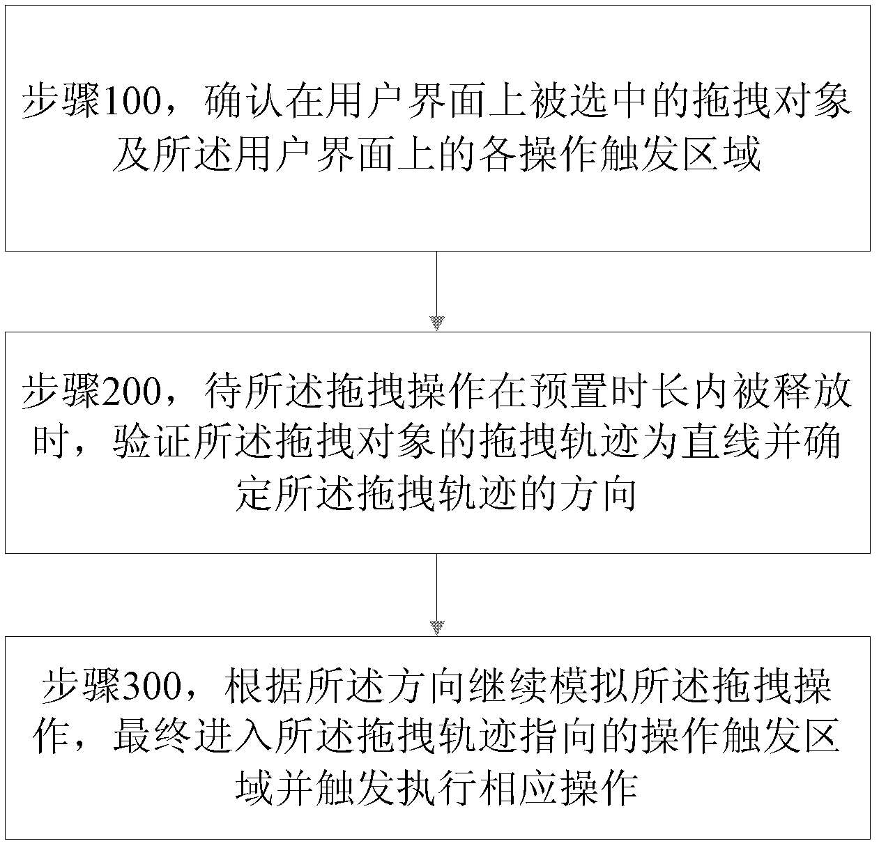
[0035]The core idea of ​​the present invention is to: confirm the selected mobile object on the user interface and each operation trigger area on the user interface; and verify the movement of the mobile object when the movement operation is released within a preset time length The trajectory is a straight line and the direction of the movement trajectory is determined; the movement operation is continuously simulated according to the direction, and finally enters the operation trigger area pointed by the movement trajectory and triggers the execution of the corresponding operation.

[0036] The moving operation is an operation of continuously moving t...


PUM


Abstract

The invention discloses a user interface based operation triggering method, a user interface based operation triggering device and terminal equipment. The operation triggering method includes: determining a selected moving object on a user interface and each operation triggering area on the user interface; when a moving operation is released in a preset time, verifying whether the moving track of the moving object is linear or not and determining the direction of the moving track; continuing simulating the moving operation of the moving object according to the direction of the moving track; and finally, entering the operation triggering area directed by the moving track and trigging and executing the corresponding operation. By the aid of the method, the device and the terminal equipment, the moving distance can be greatly shortened, the moving object can be automatically moved to the operation triggering areas by comprehending the intention of a user according to intelligent judgment on the direction, speed and distance of the operation, and the corresponding operation can be completed without moving the moving object to an assigned position, so that the moving operation is greatly simplified and operation cost is reduced.

Description

technical field [0001] The invention belongs to the field of computers, and in particular relates to a user interface-based operation triggering method, device and terminal equipment. Background technique [0002] Today's user interface, whether it is based on a touch screen or a traditional display screen, can be used as a human-computer interaction portal by placing buttons and icons on the user interface, and the user can complete the corresponding operation by clicking the button and / or icon. [0003] In addition to the above-mentioned click operation, there is also a drag operation mode. The user selects an object on the user interface, moves it to a button area on the user interface, and then releases the object, and the object activates the button in the button area and executes an instruction corresponding to the button. For example: on an Android mobile phone, when deleting an application icon on the user's desktop, the application icon can be changed to a selected...

Claims


Application Information

Patent Timeline
IPC IPC(8): G06F3/048G06F3/0481G06F3/0484
Inventor 董宇
Owner BEIJING QIHOO TECH CO LTD
Learn More