
Super-smooth surface defect detection system and distortion correction method thereof

An ultra-smooth surface and defect detection technology, applied in the direction of optical testing flaws/defects, can solve problems such as high cost of optical design, result length, curvature error, defect fracture, etc.

Active Publication Date: 2013-06-12
ZHEJIANG UNIV
View PDF6 Cites 0 Cited by
  • Summary
  • Abstract
  • Description
  • Claims
  • Application Information

AI Technical Summary

Problems solved by technology

If this distortion is not corrected before the sub-images are image-processed, stitching of adjacent sub-aperture images may result in breakage of defects (especially scratches) in overlapping areas; Errors in the results of the feature recognition process (e.g. length, curvature) for defects
Under the premise of ensuring the parameters required by the ultra-smooth surface defect detection system, changing the optical design is costly and difficult to achieve

Method used


Image

  • Super-smooth surface defect detection system and distortion correction method thereof
  • Super-smooth surface defect detection system and distortion correction method thereof
  • Super-smooth surface defect detection system and distortion correction method thereof

Examples


Embodiment

[0067] An example of the application of the present invention to an ultra-smooth surface defect detection system and its distortion correction method is as follows.

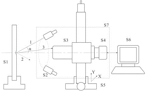
[0068] Such as figure 1 As shown, the ultra-smooth surface defect detection system includes a two-dimensional guide device S5, a computer S6, an optical microscopic imaging device S7, a standard plate S8 and a clamping device S9 for the standard plate, and the optical microscopic imaging device S7 includes an LED ring lighting source S2, zoom microscope S3, CCD detector S4; CCD detector S4, zoom microscope S3, and LED ring lighting source S2 are sequentially connected to form the optical microscopic imaging device S7 of the detection system, and the CCD detector S4 communicates with the detector through a communication cable. The computer S6 is connected, the optical microscopic imaging device S7 is placed on the two-dimensional shifting device S5, and the two-dimensional shifting device S5 drives the optical mic...


PUM


Abstract

The invention provides a super-smooth surface defect detection system and a distortion correction method thereof. The invention aims to solve the problem that defects are fractured when subimages are spliced due to the fact that optical distortion exists in the super-smooth surface defect detection system. The invention is technically characterized in that the super-smooth surface defect detection system, a distortion correction on-gauge plate and a clamping device for the on-gauge plate are designed. The on-gauge plate is collected to obtain a distortion image of a dark field by utilizing the detection system; a distortion degradation model is established through the distortion image and a computer by matching with an ideal image of the on-gauge plate reconstructed according to the relation between the dimension of an object plane and the pixel of an image plane, and the distortion correction method based on secondary polar coordinate positive and negative transformation and secondary gray level linear interpolation is provided. The method can be used for correcting the distortion in the super-smooth surface defect detection system to avoid splicing dislocation of adjacent subimages, and meanwhile, is also suitable for correcting the distortion existing in other wide-field optical systems based on image splicing.

Description

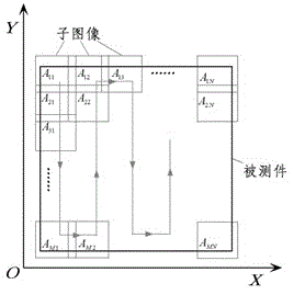
technical field [0001] The invention relates to a distortion correction method of an ultra-smooth surface defect detection system. Background technique [0002] Quantitative detection of surface defects of large-scale precision optical components has always been one of the internationally recognized optical detection problems. The surface to be inspected is at the macroscopic level, and the defects to be resolved on the surface sometimes need to be at the microscopic to micron level. The "ultra-smooth surface defect detection system" developed by the inventors can realize automatic detection and digital evaluation of surface defects of precision optical components by using technologies such as optical micro-scattering dark-field imaging, sub-image scanning, and stitching based on feature matching. The ultra-smooth surface defect detection system can complete automatic quantitative detection of full-aperture surface defects of optical components with a maximum size of 430mm×...

Claims


Application Information

Patent Timeline
Patent Type & Authority Patents(China)
IPC IPC(8): G01N21/95
Inventor 杨甬英王世通曹频陈晓钰卓永模
Owner ZHEJIANG UNIV
Learn More