
Optical splitting system of flattening convex surface grating

A convex grating and spectroscopic system technology, applied in the field of spectroscopic instruments, can solve the problems of complex structure of the spectroscopic system, high requirements for production, installation and debugging, and achieve the effects of wide application range, low production cost and convenient installation

Inactive Publication Date: 2012-09-12
UNIV OF SHANGHAI FOR SCI & TECH
View PDF4 Cites 9 Cited by
  • Summary
  • Abstract
  • Description
  • Claims
  • Application Information

AI Technical Summary

Problems solved by technology

[0004] The present invention is aimed at the problem that the structure of the current light splitting system is relatively complicated, and the requirements for manufacture, installation and debugging are relatively high, and a flat image field convex grating light splitting system is proposed.

Method used


Image

  • Optical splitting system of flattening convex surface grating
  • Optical splitting system of flattening convex surface grating
  • Optical splitting system of flattening convex surface grating

Examples


Embodiment Construction

[0012] The present invention will be described in detail below in conjunction with the accompanying drawings and embodiments.

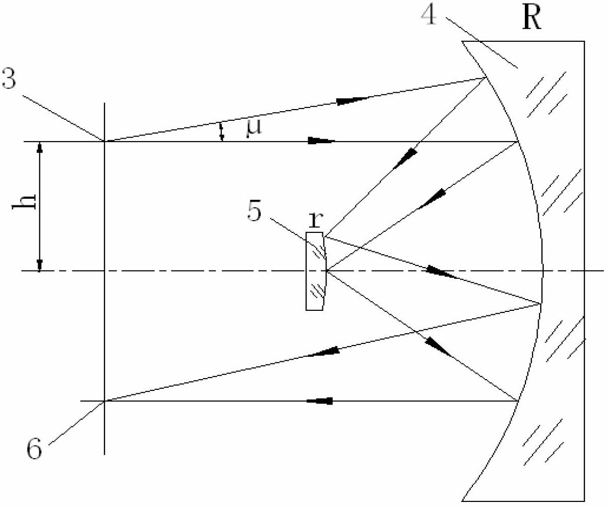
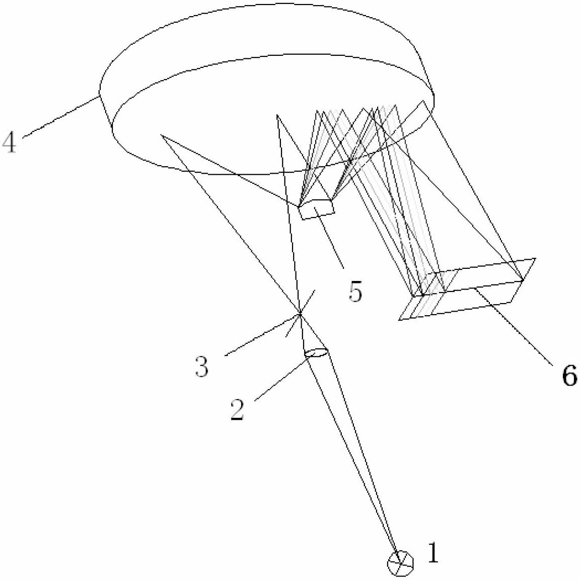
[0013] The structure of the flat image field convex grating spectroscopic system is as follows: figure 1 Shown: includes light source 1, condenser lens 2, entrance slit 3, large concave mirror 4, convex grating 5 and area array detector 6.

[0014] The steps to build a convex grating spectroscopic system are as follows:

[0015] 1. Select a convex grating 5 and a large concave reflector 4, so that the radius r of the convex grating is greater than the radius R / 2 of the concave reflector, namely:

[0016] 2. Place the spherical center of the convex grating 5 and the large concave reflector 4 on the same point, and the optical axes coincide to establish a concentric and coaxial light splitting system.

[0017] 3. Place the incident slit 3 in the plane that passes through the common spherical center of the convex grating 4 and the large concave refle...


PUM


Abstract

The invention relates to an optical splitting system of a flattening convex surface grating, comprising a light source, a light condenser, an incident narrow slot, a large-concave-surface reflecting mirror, a convex-surface grating and a surface array detector, wherein the sphere centers of the convex-surface grating and the large-concave-surface reflecting mirror are arranged on a same point, optical shafts are superposed, the incident narrow slot is arranged at a public sphere center of the convex-surface grating and the large-concave-surface reflecting mirror and is vertically arranged in a plane of a public optical shaft, the direction of the incident narrow slot is parallel to a notching direction of a grating, the surface array detector is arranged at the public sphere center of the convex-surface grating and the large-concave-surface reflecting mirror and is vertically arranged in the plane of the public optical shaft, the surface array detector and the incident narrow slot are arranged on two sides of the optical shaft, and white lights emitted by the light source are radiated to the large-concave-surface reflecting mirror through a focus lens and the incident narrow slot, is reflected and radiated to the convex-surface grating through the large-concave-surface reflecting mirror, is radiated onto the large-concave-surface reflecting mirror after passing through a diffracted wave diffracted by the convex-surface grating, and is finally converged to the surface array detector through the large-concave-surface reflecting mirror. The optical splitting system disclosed by the invention has the advantages of high spectrum resolution, approximative zero of spectral image distortion, simple structure, convenience in installation and low manufacturing cost.

Description

technical field [0001] The invention relates to a spectroscopic instrument, in particular to a flat image field convex grating spectroscopic system. Background technique [0002] The spectroscopic system is the core component of the spectroscopic analysis instrument. At present, planar gratings or concave gratings are generally used as spectroscopic elements. A spectroscopic system using a planar grating as a spectroscopic element requires a mechanical scanning structure to achieve spectral analysis. The concave grating as the spectroscopic element can adopt a scanning structure, or use the focusing effect of the concave grating to continuously distribute the spectrum on a plane, and use it in combination with an area array detector to achieve high-speed analysis and miniaturization of the instrument and lightweight. However, the dispersion spectrum of the flat image field concave grating spectroscopic system has relatively serious aberrations, which brings difficulties in...

Claims


Application Information

Patent Timeline
IPC IPC(8): G01J3/18G02B27/10
Inventor 李柏承黄元申张大伟倪争技夏俊庄松林
Owner UNIV OF SHANGHAI FOR SCI & TECH
Learn More