Method and system for detecting linearity and rigidity of bridges and tunnels on basis of fiber-optic gyroscope technology
A fiber optic gyroscope and detection method technology, which is applied to the testing of machine/structural components, measurement devices, and optical devices, etc., can solve the problems of difficult monitoring scale, complicated measurement point burial, lack of position correction algorithm and local filtering algorithm, etc. , to achieve the effect of improving the accuracy
- Summary
- Abstract
- Description
- Claims
- Application Information
AI Technical Summary
Problems solved by technology
Method used
Image
Examples
Embodiment 1
[0063] Linear measurements on bridge surfaces:
[0064] see Figure 7 , the alignment detection walking device 10 is attached to the bridge alignment test area 54 to walk, and selects reference points 55 that can be regarded as fixed along the line, such as bridge piers, and measurement reference points 52 at both ends of the bridge for error correction. When the linear detection walking device 10 is tested each time, a known fixed reference point 52 is fixed at one end to ensure that each phase of the test has the same measurement starting point. get as Figure 6 The original linear measurement curve 41, when the linear detection walking device passes the fixed reference point 52 on the other side and the fixed reference point 55 along the way, since the coordinate information of such points is known, it can be used as the boundary of the continuous linear trajectory data Constraint conditions, use the aforementioned algorithm (2) to reversely correct and segmentally calcul...
Embodiment 2
[0066] Linear measurement along the tunnel direction and cross-section in the tunnel:
[0067] See respectively Figure 8 and Figure 9, for the alignment test of the tunnel driving direction, the external reference point 61 of the tunnel entrance is used as the measurement starting point, and the fixed reference point 61 is passed through the alignment detection along the tunnel direction to ensure that each phase of the test has the same measurement starting point. The linear test area 64 along the tunnel is tested, and the raw data of the gyroscope is processed by algorithm (1) and then the original trajectory algorithm is used to obtain the following: Figure 6 The original alignment measurement curve 41, the reference point 62 of the area with better surrounding rock conditions passed by the alignment detection walking device and the fixed reference point 61 outside the tunnel on the other side can be used as the boundary of the continuous alignment trajectory data becau...
Embodiment 3
[0069] Linear measurement of mine tanks or elevator shafts:
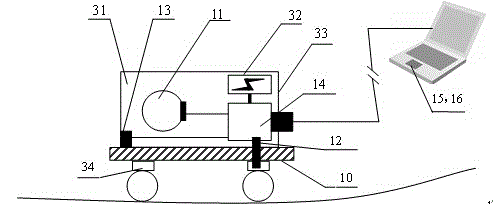
[0070] The rigid tank of the mine tank is generally installed directly on the underground rock, which is easily affected by the underground geological structure and causes a jamming accident. By adopting the device of the invention, the linear curve of the tank can be regularly detected, and the reliability of safe operation of the current tank can be evaluated. For its implementation see Figure 10 , the test integration device 31 is installed in the cage lifting container 85 , and the linear speed sensor 12 is installed on the roller tank ears 83 . In this example, the gyroscope in the test integration device 31 may be a three-axis gyroscope. During the test, the lifting container 85 carries the test integration device 31 attached to the rigid tank 84 and advances along the lifting direction 86 . Use the algorithm (1) to process the raw data of the gyroscope, and then use the aforementioned original trajectory ...
PUM
 Abstract
Description
Claims
Application Information
 - R&D
- Intellectual Property
- Life Sciences
- Materials
- Tech Scout
- Unparalleled Data Quality
- Higher Quality Content
- 60% Fewer Hallucinations
Browse by: Latest US Patents, China's latest patents, Technical Efficacy Thesaurus, Application Domain, Technology Topic, Popular Technical Reports.
© 2025 PatSnap. All rights reserved.Legal|Privacy policy|Modern Slavery Act Transparency Statement|Sitemap|About US| Contact US: help@patsnap.com


