Lamp fitting construction members and ceiling lamp using same

A technology of lamps and components, which is applied to the parts of lighting devices, lighting devices, fixed lighting devices, etc., can solve problems that affect the stability and appreciation of lamps, parts fall off, and the danger is self-evident, etc., to achieve lighting environment Soft and layered, reducing production and assembly costs, avoiding dark shadows and light spots

Active Publication Date: 2012-09-12
JIANGSU TIWIN OPTO ELECTRONICS TECH
View PDF5 Cites 3 Cited by
  • Summary
  • Abstract
  • Description
  • Claims
  • Application Information

AI Technical Summary

Problems solved by technology

[0002] Most of the existing lamps install each lamp component on each lamp arm. The installation method is relatively old, and the artistic appreciation is not high. The scattered design of each component on the lamp arm makes part of the light emitted by the light source blocked or softened by the component. , while other light rays are directly emitted through the gaps between the components, forming shadows and light spots on the overall lighting environment, resulting in uneven lighting and no layering
[0003] At the same time, the connection relationship between the various components on traditional lamps is mostly fixed by bolts. For lamps with more complex shapes, the more lamp components it contains, the more bolts used to connect the components, which makes the product cost and The labor cost of assembly increases, and the assembly man-hour will also be extended
[0004] Moreover, the bolt assembly is greatly affected by human factors. If the screw torque is too small, the bolts will not be driven in place, which may cause loose connections between components and shake from side to side, affecting the overall stability and appreciation of the lamp; If the bolt torque is too large, the bolt will slip, which may cause the corresponding parts to fall off. For large lamps, especially chandeliers, the danger of using it is self-evident

Method used


Image

  • Lamp fitting construction members and ceiling lamp using same
  • Lamp fitting construction members and ceiling lamp using same
  • Lamp fitting construction members and ceiling lamp using same

Examples


Embodiment Construction

[0058] Below in conjunction with embodiment the present invention is described in further detail:

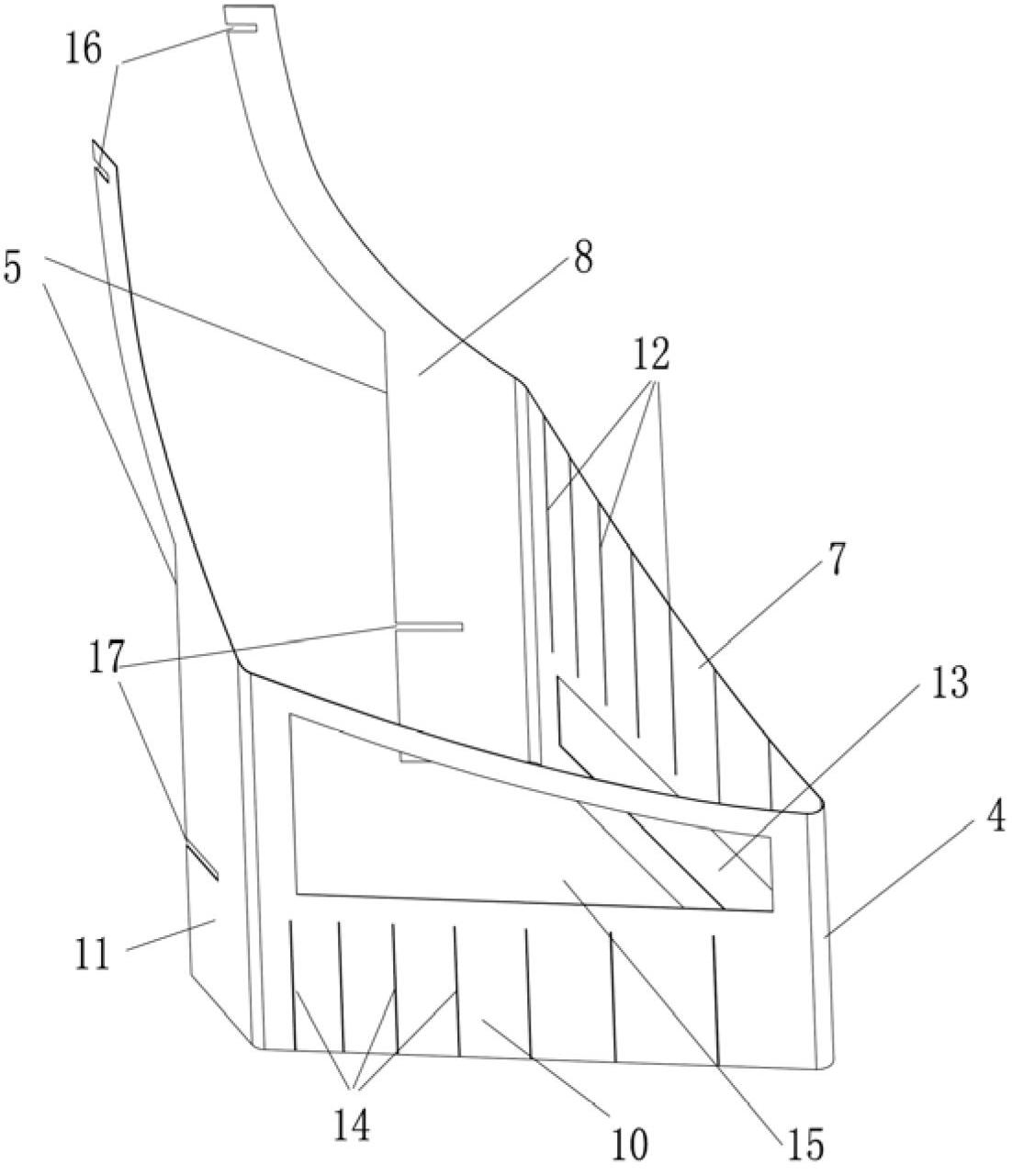
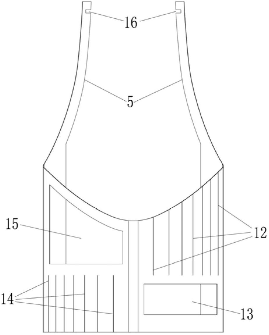
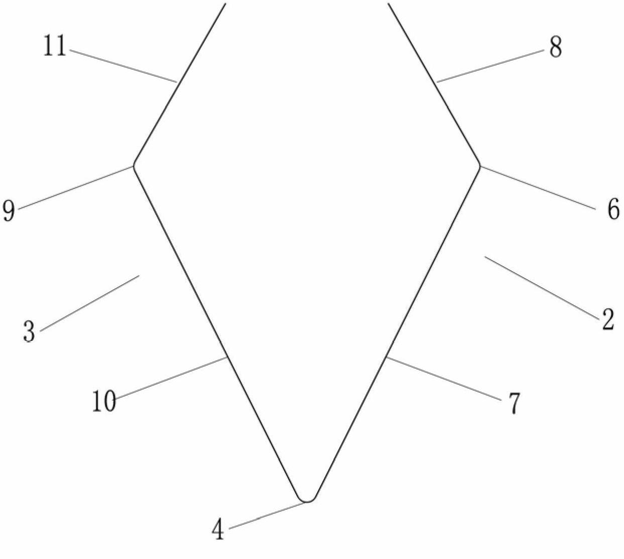
[0059] A lamp component 1, which includes a front half page 2 and a reverse half page 3 and a common edge 4 connecting the front half page 2 and the reverse half page 3, the front half page 2 and the reverse half page 3 are folded in half along the common edge 4, and the front half Page 2 and reverse half page 3 respectively form a free edge 5 away from the common edge 4, and positive half page 2 and reverse half page 3 form an opening between the two free edges 5;

[0060] The front half page 2 and the reverse half page 3 each also include an upper edge and a lower edge connecting the common side 4 and the free side 5;

[0061] The upper edges of the positive half page 2 and the reverse half page 3 extend downward along an arc from the tops of the respective free edges 5 to the top of the common edge 4; the lower edges of the positive half page and the reverse half page extend ...


PUM


Abstract

The invention relates to lamp fitting construction members and a ceiling lamp, wherein each lamp fitting construction member comprises a forward half leaf, a backward half leaf as well as a shared edge connected with the forward half leaf and the backward half leaf; the forward half leaf and the backward half leaf are folded along the shared edge and form a free edge far away from the shared edge, and an open mouth is formed between two free edges; at least one upper insertion groove with an upward opening is formed at the upper edge part of the forward half leaf; and at least one lower insertion groove with a downward opening and corresponding to the upper insertion groove is formed at the lower edge part of the backward half leaf. The lamp fitting construction members are used for the ceiling lamp, and six lamp fitting construction members are inserted and installed through upper insertion grooves and lower insertion grooves. The lamp fitting construction members and the ceiling using the lamp fitting construction members provided by the invention are simple in structure and convenient to assemble, and have good decoration effects.

Description

Technical field: [0001] The invention relates to the lighting field, in particular to a lamp component and a chandelier using the lamp component. Background technique: [0002] Most of the existing lamps install each lamp component on each lamp arm. The installation method is relatively old, and the artistic appreciation is not high. The scattered design of each component on the lamp arm makes part of the light emitted by the light source blocked or softened by the component. , while other light rays are directly emitted through the gaps between the components, forming dark shadows and light spots on the overall lighting environment, resulting in uneven lighting and no sense of hierarchy. [0003] At the same time, the connection relationship between the various components on traditional lamps is mostly fixed by bolts. For lamps with more complex shapes, the more lamp components it contains, the more bolts used to connect the components, which makes the product cost and The...

Claims


Application Information

Patent Timeline
Patent Type & Authority Applications(China)
IPC IPC(8): F21V21/10F21S8/06
Inventor 区其富
Owner JIANGSU TIWIN OPTO ELECTRONICS TECH
Why Eureka
Try Eureka