
Air filter mechanism for small-sized vehicle

An air filter, vehicle technology, applied in the direction of fuel air filter, combustion air/combustion-air treatment, bicycles, etc., can solve the problem of the inability to solve the installation space of the suction temperature sensor, the difficulty of installation and removal or maintenance, and the problem of suction To avoid issues such as air ventilation resistance, achieve stable detection values, easy installation, removal or maintenance, and prevent stenosis

Active Publication Date: 2012-09-05
HONDA MOTOR CO LTD
View PDF5 Cites 7 Cited by
  • Summary
  • Abstract
  • Description
  • Claims
  • Application Information

AI Technical Summary

Problems solved by technology

[0006] In the structure shown in the above-mentioned Patent Document 1, it can also be said that the air intake temperature sensor is installed on the air cleaner supported by the swing type power unit, but the purpose of the intake air temperature detection is different. In addition, the shown In the structure of the air filter, the main body of the suction temperature sensor and the temperature-sensitive control valve are arranged in the center of the clean room of the air filter, so the clean room is narrow, the installation and removal or maintenance are difficult, and the suction air cannot be solved. The problem of the installation space of the temperature sensor
In addition, the ventilation resistance that causes inhalation is also problematic as an inhalation structure.

Method used


Image

  • Air filter mechanism for small-sized vehicle
  • Air filter mechanism for small-sized vehicle
  • Air filter mechanism for small-sized vehicle

Examples


Embodiment Construction

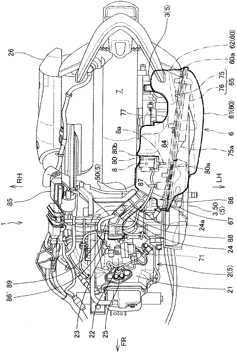
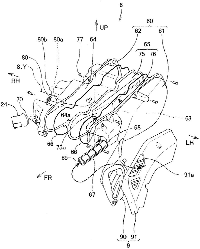
[0078] Below, based on Figure 1 to Figure 7 , a structure of an air cleaner for a small vehicle according to an embodiment of the present invention will be described.

[0079] It should be noted that directions such as front, rear, left, right, up, and down in the description of this specification and the claims are based on the fact that the swing type power unit supporting the air cleaner according to this embodiment is mounted on a vehicle, especially a small vehicle such as a motorcycle. The direction of the vehicle in the state. In the drawings, arrow FR indicates the front of the vehicle, LH indicates the left side of the vehicle, RH indicates the right side of the vehicle, and UP indicates the upper side of the vehicle.

[0080] In addition, in the figure, marked black small arrows schematically indicate the flow of intake air taken in from outside air, and hollow small arrows schematically indicate the flow of intake air passing through the filter part of the air fil...


PUM


Abstract

The invention provides an air filter mechanism for a small-sized vehicle, in an air filter supported at a swing power unit, space for installing an air temperature sensor and a preferable air temperature detecting environment are guaranteed, and a more effective air structure is formed. The mechanism has an air filter (6) provided on one side of a driving wheel and supported by a swing power unit (5). The swing power unit is swingably mounted in a vertical direction to a body frame (4). The air filter mechanism for a small-sized vehicle is characterized in that, a rear end of the air filter housing is disposed at a position closer to the back part than a back buffer member, and a filter portion is disposed at a position overlapped with the back buffer member from a side view. A clean air chamber is provided in an air filter housing such that a front side of the chamber close to the housing is enlarged. A connection pipe is connected to an internal combustion engine and mounted to the chamber. The air temperature sensor determines a temperature of the fed air and is mounted to an outer surface of the housing such that a probe of the sensor is inserted into the chamber.

Description

technical field [0001] The present invention relates to the structure of an air cleaner for a small vehicle such as a motorcycle or a buggy using a swing-type power unit. Background technique [0002] In recent years, fuel injection (Fuel Injection) has been implemented in small vehicles such as motorcycles and small motor vehicles using swing-type power units. In this case, in order to control the fuel injection device, it is necessary to install an air intake temperature sensor, but for the air filter supported by the swing power unit, the upper installation space is limited by the frame, the installation space on the center side of the vehicle is limited by the rear wheels, and the rear installation space is limited by the rear buffer, so Securing a space for installing the intake air temperature sensor becomes more of a problem. [0003] Furthermore, it is required to ensure a more preferable intake air temperature detection environment and a more effective intake struc...

Claims


Application Information

Patent Timeline
IPC IPC(8): F02M35/024F02M35/04
CPCF02M35/162B62K2202/00
Inventor 三川诚清水孝彦
Owner HONDA MOTOR CO LTD
Learn More