Device and process for regenerating active carbon
A regeneration device and activated carbon technology, which is applied in filter regeneration, petroleum industry, filtration and separation, etc., can solve the problems of small amount of activated carbon and low regeneration efficiency at one time, and achieve simple production device, large regeneration capacity and high regeneration degree Effect
- Summary
- Abstract
- Description
- Claims
- Application Information
AI Technical Summary
Problems solved by technology
Method used
Image
Examples
Embodiment 1
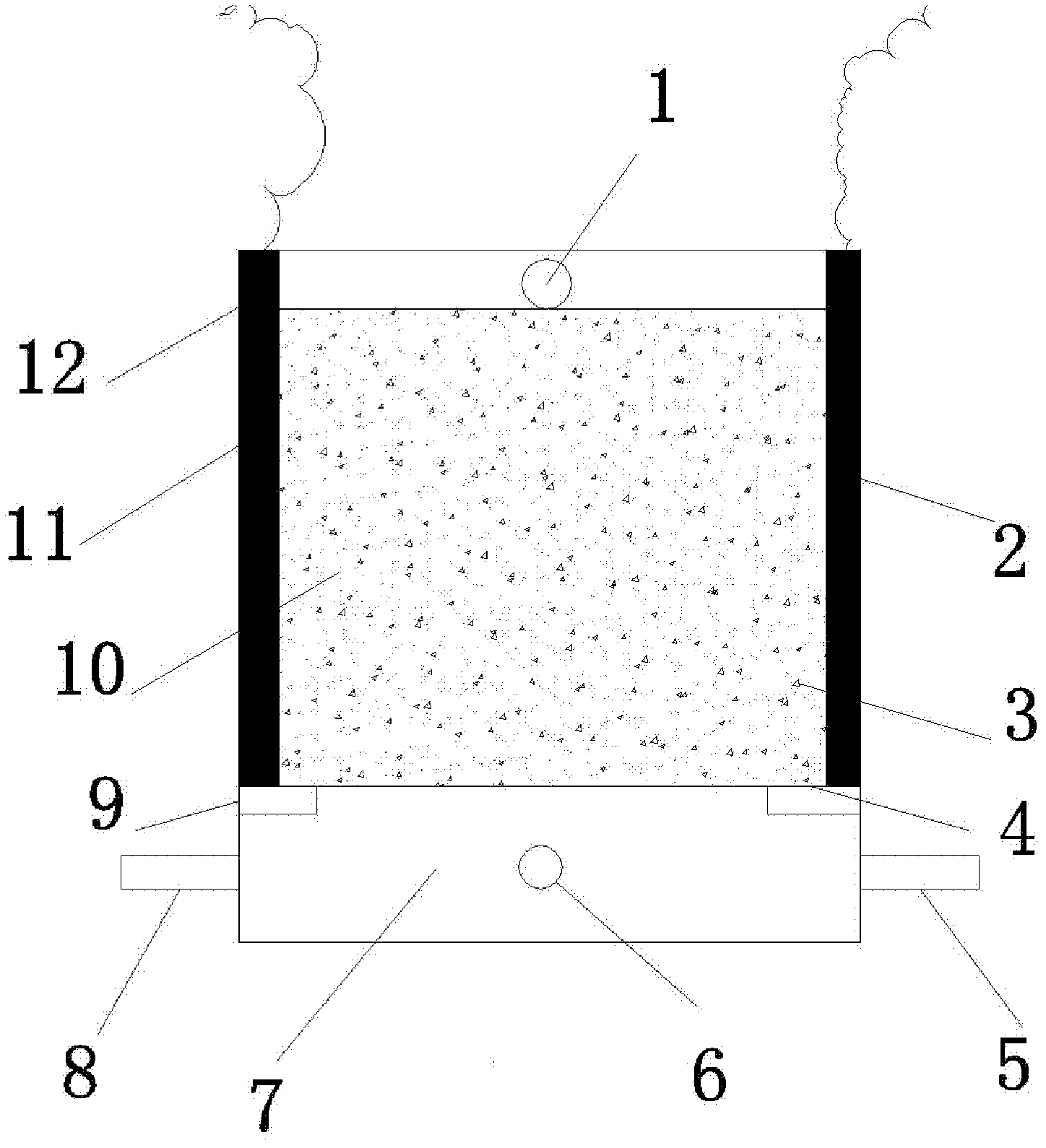
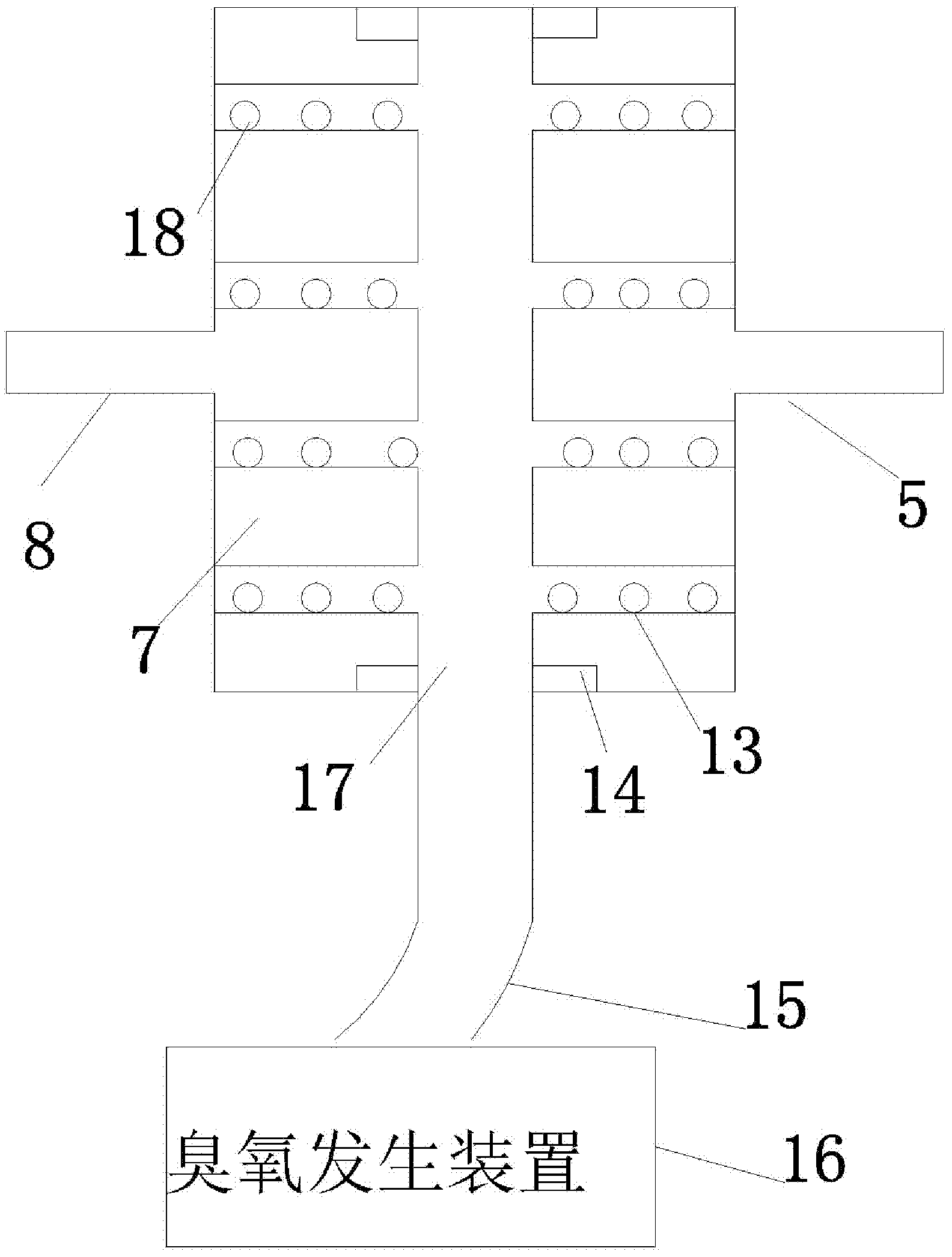
[0018] Such as figure 1 As shown: plexiglass is used as the material of the shell and the hydraulic distribution plate. The shell is a cuboid, and the hydraulic distribution plate is placed on the baffle tightly bonded to the inner wall of the device. The hydraulic distribution plate divides the device into the reaction chamber and the exposure chamber. In the gas chamber, graphite electrodes are respectively set on the side walls of the relative position of the reaction chamber as anode and cathode. The anode and cathode are connected to the power supply through wires. The air inlet is connected to the ozone generator, the aeration pipes are arranged in the shape of "Feng", and the branch pipes of the aeration pipes are uniformly opened with round holes as aeration holes, and each of them is opened at the relative position of the side wall parallel to the main pipe of the aeration hole. The circular hole acts as an inlet for contaminated water and electrolyte.
Embodiment 2
[0020] The structure of the device is as in Example 1, wherein the ratio of the reaction chamber to the aeration chamber is 3:1, the thickness of the electrode is 10mm, the aperture of the aeration inlet is 8mm, the aperture of the aeration hole is 2mm, and the aperture of the electrolyte inlet is 10mm , put 400g of activated carbon into the reaction chamber, pump 500mg / L of phenol solution into the reaction chamber through the polluted water inlet at a speed of 8ml / min, measure the concentration of phenol when the water is discharged, and stop pumping after 2L of polluted water is processed, Close the polluted water inlet and open the regeneration solution inlet, pump the NaCl electrolyte (concentration: 3g / L) into the reaction chamber at a rate of 8ml / min, when the electrolyte just covers the activated carbon layer, turn on the power and adjust the current to 0.1A , turn on the ozone generator for regeneration, adjust the intake flow to 0.3L / min, the electrolyte flows out fro...
Embodiment 3
[0022] The structure is as in Example 1, the ratio of the reaction chamber and the aeration chamber is 4:1, the thickness of the electrode is 10mm, the aperture of the aeration inlet is 8mm, the aperture of the aeration hole is 2mm, the aperture of the electrolyte inlet is 10mm, and 500g Put the activated carbon into the reaction chamber, pump 2000mg / L phenol solution into the reaction chamber through the polluted water inlet at a rate of 5ml / min, measure the concentration of phenol when the water is discharged, stop pumping and close the polluted water after 2L of polluted water is treated Open the regeneration solution inlet at the inlet, pump the NaCl electrolyte (with a concentration of 5g / L at a rate of 25ml / min) into the reaction chamber, when the electrolyte just covers the activated carbon layer, turn on the power, adjust the current to 0.3A and turn on the ozone generator For regeneration, adjust the air intake flow rate to 0.6L / min, and the electrolyte flows out from ...
PUM
 Abstract
Description
Claims
Application Information
 - R&D
- Intellectual Property
- Life Sciences
- Materials
- Tech Scout
- Unparalleled Data Quality
- Higher Quality Content
- 60% Fewer Hallucinations
Browse by: Latest US Patents, China's latest patents, Technical Efficacy Thesaurus, Application Domain, Technology Topic, Popular Technical Reports.
© 2025 PatSnap. All rights reserved.Legal|Privacy policy|Modern Slavery Act Transparency Statement|Sitemap|About US| Contact US: help@patsnap.com


