
Vacuum-state centrifugal filtering and dehydrating device for lubricating oil

A technology of filtration dehydration and centrifugal filtration, which is applied in the direction of liquid separation, separation method, liquid separation auxiliary equipment, etc. It can solve the problem of low filtration accuracy of jet centrifuge, inability to filter emulsified water of lubricating oil, inconvenience of transportation and movement and other problems, to achieve the effect of convenient and fast transportation and movement, light weight and few parts

Inactive Publication Date: 2012-09-05
BAOJI HENGTONG ELECTRONICS
View PDF3 Cites 4 Cited by
  • Summary
  • Abstract
  • Description
  • Claims
  • Application Information

AI Technical Summary

Problems solved by technology

[0002] Lubricating oil contains impurities and water, and it must be filtered or purified before use. Traditional lubricating oil filtering or purification devices use liquid jet centrifuges or vacuum oil filters, but the above two methods are There are defects. The jet centrifuge has low filtration accuracy due to the speed limit. The vacuum oil filter cannot filter out the emulsified water in the lubricating oil from the structural principle. Moreover, the above-mentioned equipment is large in size, heavy in weight, and low in working efficiency, resulting in transportation and mobility inconvenience, so it is necessary to improve

Method used


Image

  • Vacuum-state centrifugal filtering and dehydrating device for lubricating oil
  • Vacuum-state centrifugal filtering and dehydrating device for lubricating oil

Examples


Embodiment Construction

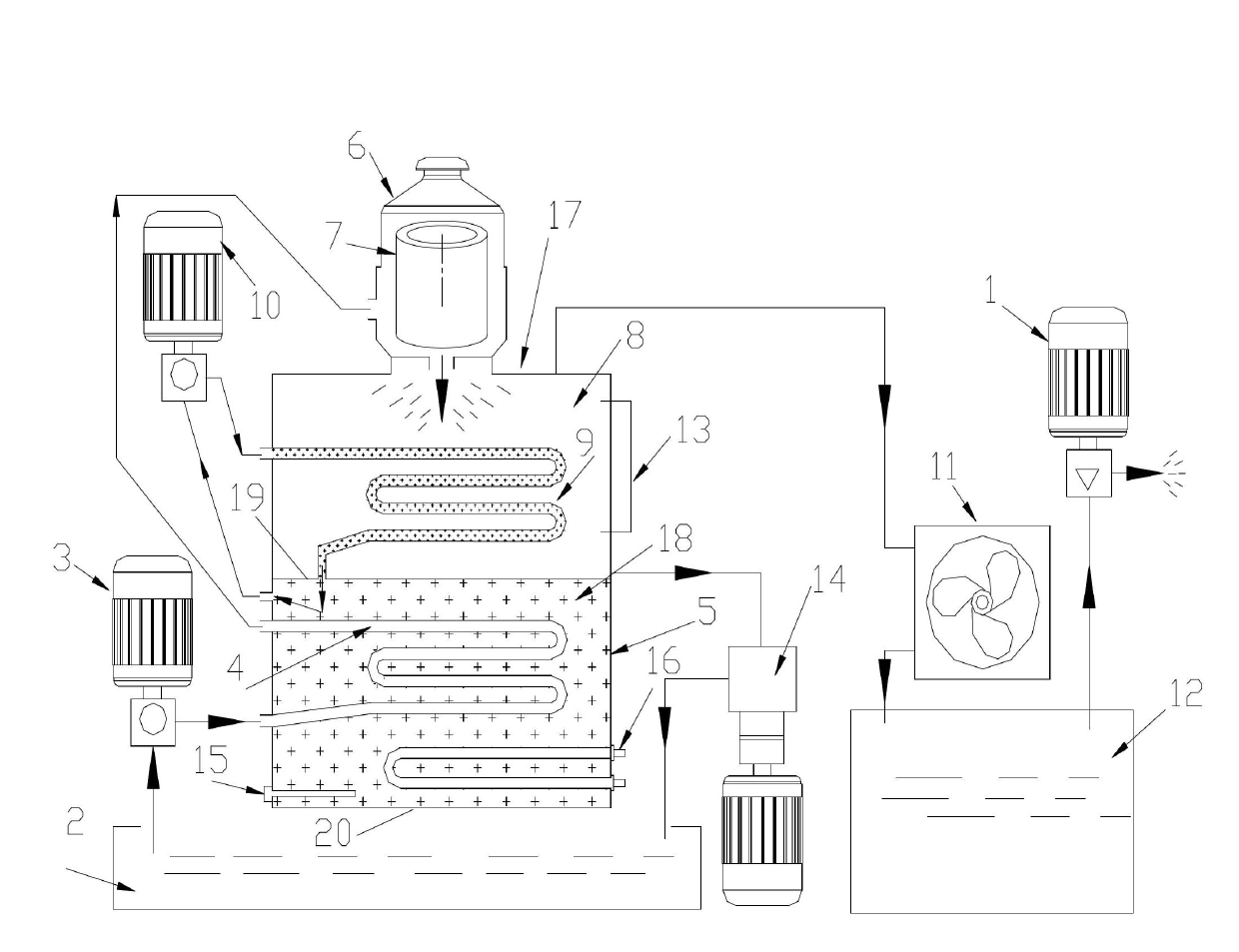
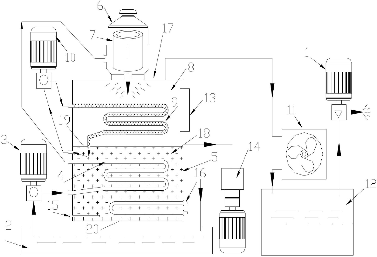
[0016] Attached below figure 1 An embodiment of the present invention is described.

[0017] The lubricating oil vacuum state centrifugal filter dehydration device has an integrated tank body 17, and the integrated tank body 17 is composed of a tank type vacuum generator 8 and a heat transfer oil heating device 5. Specifically, the heat transfer oil heating device 5 includes Heat-conducting oil tank 20, heat-collecting metal coil 4, heat-conducting oil 18 and electric heater 16, the heat-conducting oil 18 is filled with heat-conducting oil tank 20, and the heat-collecting metal coil 4 and electric heater 16 are all placed in the heat-conducting oil tank Inside the body 20 , the oil tank 2 is connected to the inlet end of the heat collecting metal coil 4 through the oil pump 3 , and the outlet end of the heat collecting metal coil 4 communicates with the centrifugal filter device 6 . The tank-type vacuum generator 8 is located above the heat-conducting oil heating device 5 and...


PUM


Abstract

The invention provides a vacuum-state centrifugal filtering and dehydrating device for lubricating oil. An integrated tank is composed of a tank-type vacuum generator and a conduction oil heating device, the tank-type vacuum generator is located above the conduction oil heating device and the tank-type vacuum generator and the conduction oil heating device are separated from each other, an oil tank is connected with an inlet end of the conduction oil heating device through an oil pump, an outlet end of the conduction oil heating device is communicated with a centrifugal filtering device arranged at the upper end of the tank-type vacuum generator, the centrifugal filtering device is communicated with the vacuum generator, the tank-type vacuum generator is internally provided with a conduction oil circulating device communicated with the conduction oil heating device, the top of the tank-type vacuum generator is connected with a vacuum pump through a condenser and a water collection tank, and the bottom of the tank-type vacuum generator is communicated with the oil tank through a high-suction oil drain pump. By adopting the device provided by the invention, moisture in the emulsified oil with the moisture content being 80% can be fully removed; since the temperature control and heat transfer manners are appropriate, the processed lubricating oil is oxidation-free, not black in color and loss-free in additive, the original quality of the oil product can be ensured and thus the vacuum-state centrifugal filtering and dehydrating device has high practical value.

Description

technical field [0001] The invention belongs to the technical field of filtering and purifying devices, and in particular relates to a lubricating oil vacuum state centrifugal filtering and dehydrating device. Background technique [0002] Lubricating oil contains impurities and water, and it must be filtered or purified before use. Traditional lubricating oil filtering or purification devices use liquid jet centrifuges or vacuum oil filters, but the above two methods are There are defects. The jet centrifuge has low filtration accuracy due to the speed limit. The vacuum oil filter cannot filter out the emulsified water in the lubricating oil from the structural principle. Moreover, the above-mentioned equipment is large in size, heavy in weight, and low in working efficiency, resulting in transportation And mobility inconvenience, so it is necessary to improve. Contents of the invention [0003] The technical problem solved by the present invention is to provide a lubric...

Claims


Application Information

Patent Timeline
IPC IPC(8): B01D17/038B01D17/12
Inventor 周建伟
Owner BAOJI HENGTONG ELECTRONICS
Learn More