
Testing device

A test device and guide rod technology, which is applied in the direction of measurement device, circuit breaker test, measurement of electricity, etc., can solve problems such as affecting test accuracy, difficulty in unified positioning, and inconsistent pressing strokes.

Inactive Publication Date: 2012-08-29
HONG FU JIN PRECISION IND (SHENZHEN) CO LTD +1
View PDF4 Cites 2 Cited by
  • Summary
  • Abstract
  • Description
  • Claims
  • Application Information

AI Technical Summary

Problems solved by technology

However, during the test, since different test devices are independent of each other, it is difficult to uniformly position them, their pressing strokes are inconsistent, and the pressing force is inaccurate, which easily affects the accuracy of the test

Method used


Image

  • Testing device
  • Testing device
  • Testing device

Examples


Embodiment Construction

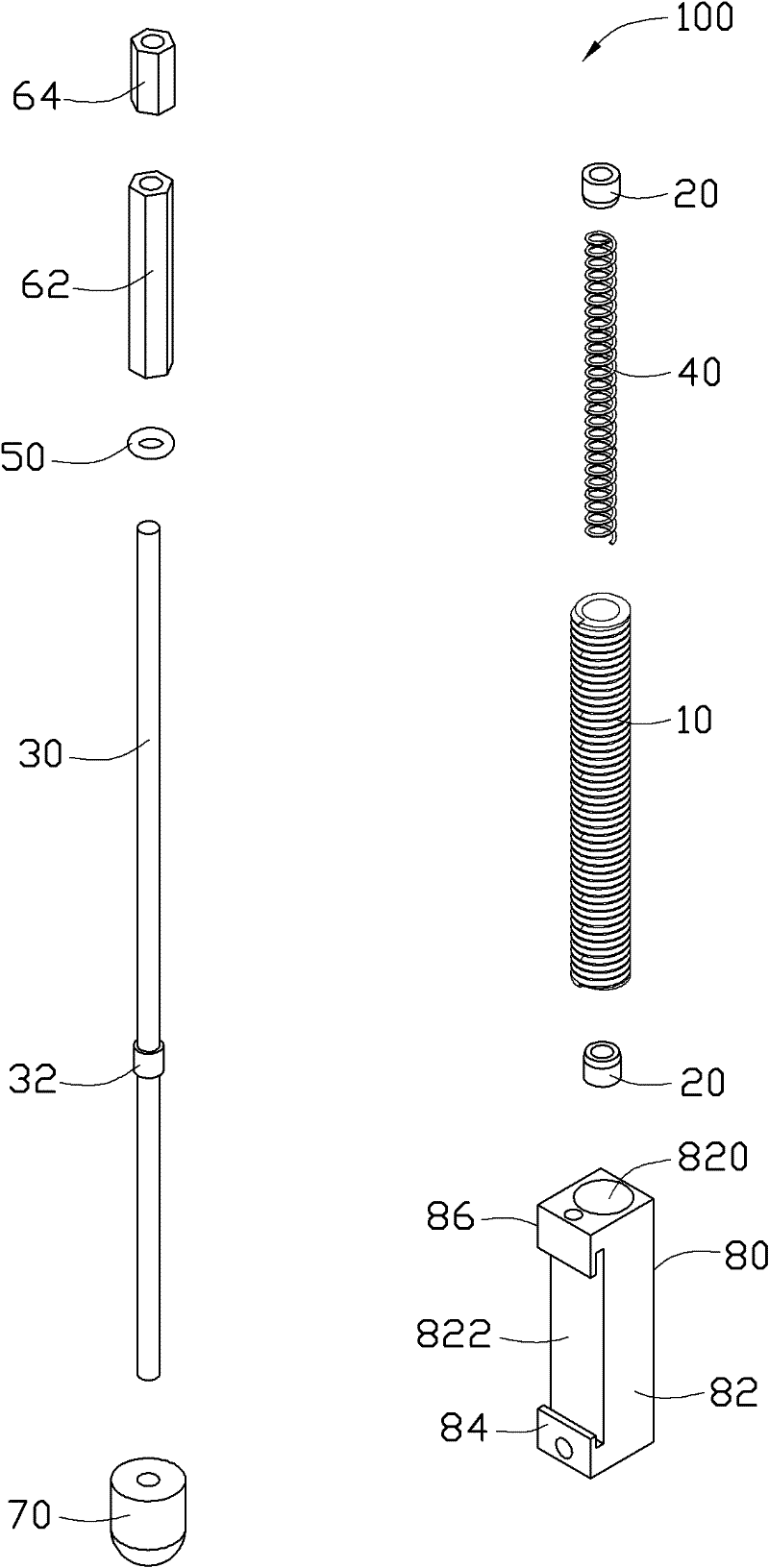
[0038] see figure 1 , the present invention discloses a test device 100, which is used to test a keyboard 200 (see Figure 4 ) reliability and service life. The testing device 100 includes a sleeve 10 , two stoppers 20 , a guide rod 30 , an elastic member 40 , a washer 50 , a first adjustment member 62 , a second adjustment member 64 , a pressure head 70 and a fixing member 80 .

[0039] The sleeve 10 is a hollow structure, and its outer peripheral wall is provided with several annular protrusions arranged at equal intervals. The two stoppers 20 are hollow cylinders, which are respectively fixed on the inner peripheral walls of the two ends of the sleeve 10 .

[0040] The guide rod 30 is slidably passed through the sleeve 10 , and a flange 32 is arranged around a substantially middle and lower portion of the guide rod 30 . The diameter of the flange 32 is slightly larger than that of the guide rod 30 . When the guide rod 30 passes through the sleeve 10 , the flange 32 abuts...


PUM


Abstract

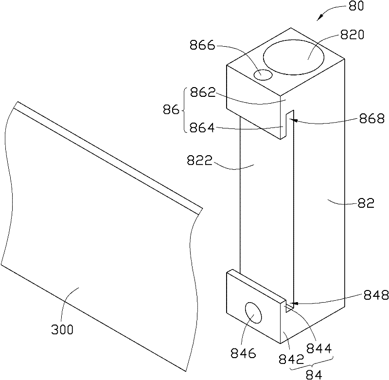
The invention provides a testing device, which includes a guide rod, an elastic piece, a press head, a sleeve and a fixed piece, wherein the elastic piece is sleeved on the guide rod, the press head is assembled at one end of the guide rod, the guide rod penetrates the sleeve in a sliding way, the elastic piece is accommodated in the sleeve, the fixed piece includes a main body, a first extending plate and a second extending plate, the sleeve is accommodated in the main body, and the first and the second extending plates are relatively arranged on the main body. The testing device is convenient to hang and take down, and has high testing precision.

Description

technical field [0001] The invention relates to a test device, in particular to a test device for testing the reliability and life of a button. Background technique [0002] Before shipment, electronic products need to go through a series of reliability tests and life tests to ensure the quality of the products. Among them, the keys of the electronic product are used to execute various functions after the user presses them. Therefore, in the reliability test of the button, repeated pressing must be performed to predict whether the button will maintain a certain quality after a long time of use. [0003] A traditional testing device includes a slider, a thimble and a spring. The spring is sleeved on the slider and resists the thimble, and the thimble corresponds to a button. When the slider moves under the action of external force, the spring and the thimble are pushed, so that the thimble presses the button, and then the slider is reset by the restoring force provided by t...

Claims


Application Information

Patent Timeline
Patent Type & Authority Applications(China)
IPC IPC(8): G01R31/327G01R1/02
CPCH04M1/23H04M1/24
Inventor 黄登聪余国俊胡永兵李元钊
Owner HONG FU JIN PRECISION IND (SHENZHEN) CO LTD
Learn More