
Detecting system for auto-passing phase-splitting function of electric locomotive

A technology of automatic phase separation and electric locomotives, which is applied in the direction of railway vehicle testing, etc., can solve problems such as high work intensity, catenary burnout, and weak sense of responsibility, and achieve the effects of convenient detection and maintenance, reliable test accuracy, and reasonable layout

Inactive Publication Date: 2012-08-29
NANJING TYCHO INFORMATION TECH
View PDF6 Cites 6 Cited by
  • Summary
  • Abstract
  • Description
  • Claims
  • Application Information

AI Technical Summary

Problems solved by technology

[0002] All electric railways adopt 27.5KV single-phase power frequency AC power supply system. In order to balance the three-phase power supply load and improve the utilization rate of the power system, the traction substation of the electrified railway adopts alternate wiring according to the phase sequence arrangement of the power system. Phase-separation facilities to prevent live-in-phase separation caused by the failure of the vehicle-mounted automatic over-phase separation system, which can easily cause phase-to-phase disconnection and catenary burnout. Big, low efficiency, weak sense of responsibility, not conducive to information management, it is necessary to adopt new technology to realize automatic over-phase detection

Method used


Image

  • Detecting system for auto-passing phase-splitting function of electric locomotive
  • Detecting system for auto-passing phase-splitting function of electric locomotive
  • Detecting system for auto-passing phase-splitting function of electric locomotive

Examples


Embodiment Construction

[0018] The present invention will be further described below in conjunction with the accompanying drawings and through specific embodiments.

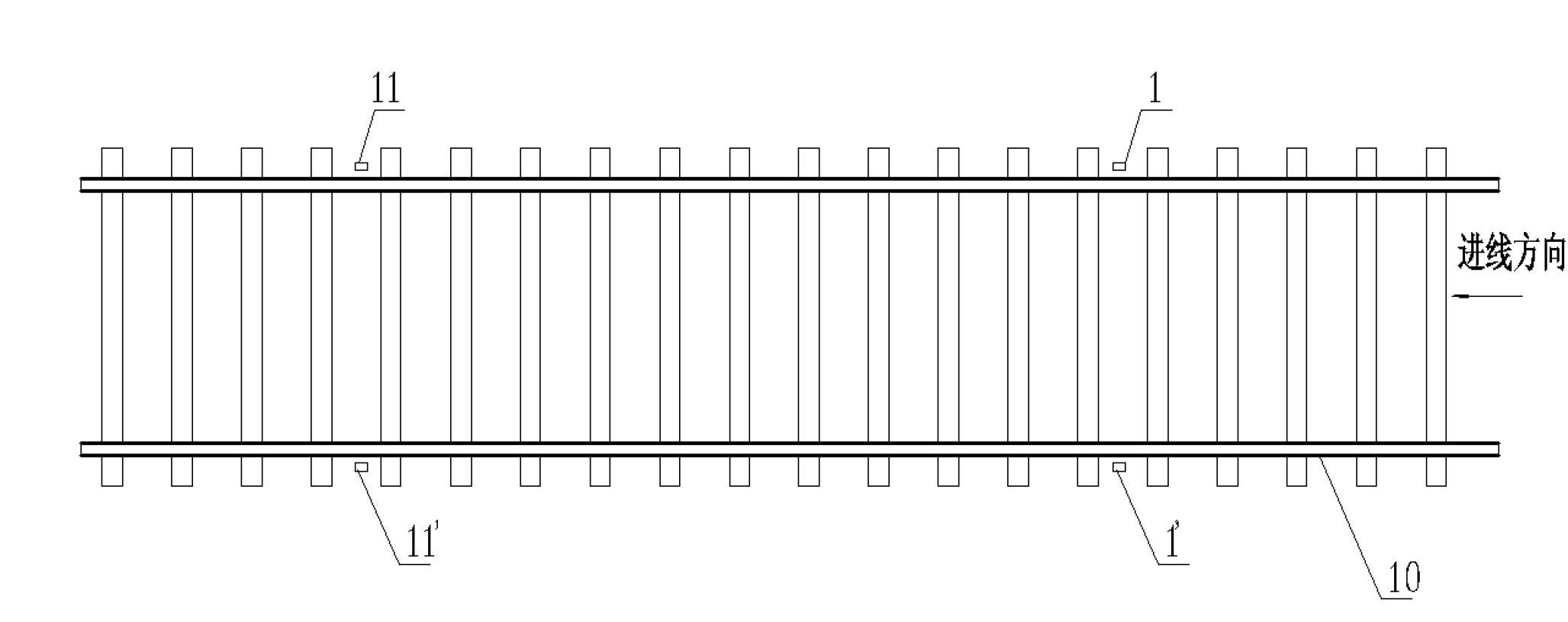
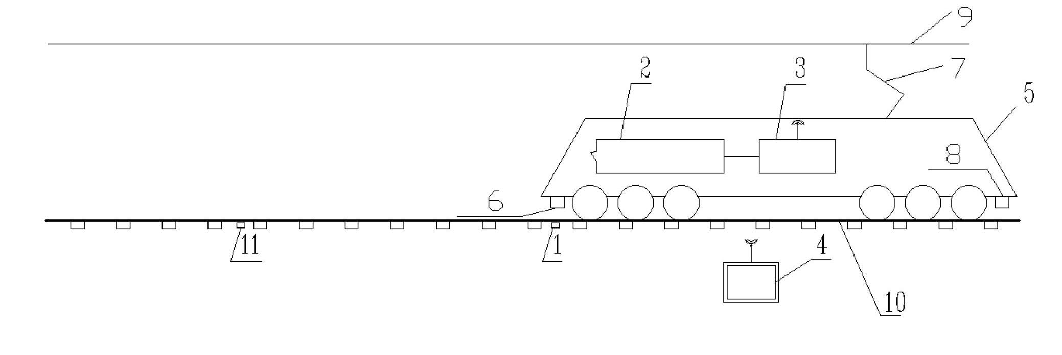
[0019] Such as figure 1 , figure 2 , an electric locomotive automatic phase separation function detection system, comprising at least a first incoming line analog ground sensor 1, a first outgoing line analog ground sensor 11, a main circuit breaker detection unit 2, a wireless transmission unit 3, and a ground measurement display unit 4 , the front induction receiver 6 and the rear induction receiver 8, the first incoming line analog ground sensor 1 and the first outlet analog ground sensor 11 are respectively arranged on one side of the track 10, the front induction receiver 6 and the rear induction The receivers 8 are respectively arranged at the front and rear ends of the electric locomotive 5, the main circuit breaker detection unit 2 and the wireless transmitter unit 3 are arranged in the electric locomotive 5, and the wireless ...


PUM


Abstract

A detecting system for an auto-passing phase-splitting function of an electric locomotive is characterized by at least comprising a first incoming line simulation ground inductor, a first outgoing line simulation ground inductor, a main circuit breaker detecting unit, a wireless transmitting unit, a ground survey display unit, a front induction receiver and a rear induction receiver, wherein both the first incoming line simulation ground inductor and the first outgoing line simulation ground inductor are arranged on one side of a track, the front induction receiver and the rear induction receiver are respectively arranged at the front and the rear ends of the electric locomotive, the main circuit breaker detecting unit and the wireless transmitting unit are arranged in the electric locomotive, and the wireless transmitting unit is connected with the ground survey display unit in a wireless mode. Due to the adoption of the technical scheme disclosed by the invention, the structure is simple, the arrangement is reasonable, the installation is convenient, the failure rate is low, the measuring accuracy is reliable, and the convenience and accuracy of detection and maintenance for the auto-passing phase-splitting function can be ensured.

Description

technical field [0001] The invention relates to an automatic phase separation function detection system for an electric locomotive, which belongs to the technical field of electric locomotives. Background technique [0002] All electric railways adopt 27.5KV single-phase power frequency AC power supply system. In order to balance the three-phase power supply load and improve the utilization rate of the power system, the traction substation of the electrified railway adopts alternate wiring according to the phase sequence arrangement of the power system. Phase-separation facilities to prevent live-in-phase separation caused by the failure of the vehicle-mounted automatic over-phase separation system, which can easily cause phase-to-phase disconnection and catenary burnout. Big, low efficiency, weak sense of responsibility, not conducive to information management, it is necessary to adopt new technology to realize automatic over-phase detection. Contents of the invention ...

Claims


Application Information

Patent Timeline
IPC IPC(8): G01M17/08
Inventor 石峥映
Owner NANJING TYCHO INFORMATION TECH
Learn More