Micro actuator with adjustable local magnetic field

A driver and magnetic field technology, applied in the direction of holding devices and electrical components using magnetic attraction or thrust, can solve the problems of electromagnetic force fluctuation edge effects and accumulated errors, complex two-stage driving methods, and limitations of degrees of freedom, etc., to eliminate Electromagnetic force fluctuation, flexible and convenient adjustment, and the effect of reducing the impact

Active Publication Date: 2012-08-22
ZHEJIANG SCI-TECH UNIV
View PDF5 Cites 5 Cited by
  • Summary
  • Abstract
  • Description
  • Claims
  • Application Information

AI Technical Summary

Problems solved by technology

[0005] The first type of linear motor drive type has the advantages of wide working range and large driving force, but there are adverse effects of electromagnetic force fluctuations, edge effects and cumulative errors
[0006] The second type of macro / micro dual driving method, which can obtain a larger operating range and higher positioning accuracy, but the degree of freedom is limited, and the two-stage driving method is more complicated
[0007] The third type uses the electromagnetic force between the coil and the permanent magnet to realize multi-degree-of-freedom drive. This structure is more flexible to adjust, but the position of the middle winding and the permanent magnet is relatively fixed, and it is easily affected by factors such as edge effects during operation, resulting in vibration.

Method used


Image

  • Micro actuator with adjustable local magnetic field
  • Micro actuator with adjustable local magnetic field
  • Micro actuator with adjustable local magnetic field

Examples


Embodiment Construction

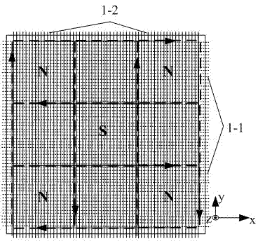
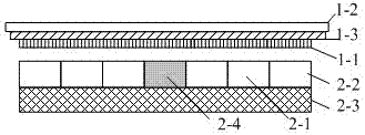
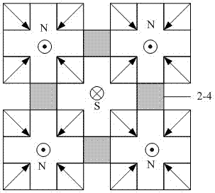
[0023] The present invention will be further described below in conjunction with the accompanying drawings and implementation methods in which the permanent magnet array is used as an example of a micro-actuator structure with five poles.

[0024] Such as figure 1 and figure 2 As shown, the present invention includes a stator composed of a two-dimensional permanent magnet array and a back iron, and a mover with armatures staggered along the X and Y axis directions or an electric armature staggered along the Y and X axes on the upper and lower surfaces of the insulator. The mover of the pivot has an air gap between the stator and the mover, which can realize the precise driving of six degrees of freedom through the action of Lorentz force; the two-dimensional permanent magnet array forms a rectangle as a whole, and the "ten"-shaped N and S main magnetic poles 2-1 is in a staggered distribution, and the adjacent N main magnetic poles or adjacent S main magnetic poles are separ...


PUM


Abstract

The invention discloses a micro actuator with adjustable local magnetic field. The micro actuator comprises stators and rotors of armatures, wherein the stators consist of a two-dimensional permanent magnet array and back iron, and the rotors of the armatures are paved on the upper surface and the lower surface of an insulation body, and the armatures are arranged along the X-axis direction and the Y-axis direction in a staggered manner, and gaps are reserved between the stators and the rotors; the two-dimensional permanent magnet array is characterized by being rectangular cross-shaped integrally, and distributing main poles N and S in a staggered manner, and the adjacent poles N or the adjacent poles S are separated by non-magnetic-conduction blocks; and the armatures arranged along the X-axis direction and the Y-axis direction in a staggered manner consist of X-axis guide wire groups in parallel arrangement and Y-axis guide wire groups in parallel arrangement. According to the micro actuator with adjustable local magnetic field, the structure is simple, the manufacturing is convenient, the adjustment of a local magnetic field and the electromagnetic force is flexible due to the guide wire type armature structure, the decoupling control on suspension force and horizontal thrust is realized, meanwhile, the micro actuator has the advantages of quick response speed, wide driving range and the like and can be used for occasions of micro-robots, photoetching machines, microelectronic packaging equipment and the like which need to be driven and operated precisely.

Description

technical field [0001] The invention relates to an electromagnetically driven micro-driver, in particular to an electromagnetic levitation micro-driver with adjustable local magnetic field. Background technique [0002] With the development of science and technology in the direction of tiny and ultra-precision fields, the objects to be manipulated by robots have also expanded from the macroscopic field to the submicron and nanoscale microscopic fields, so they can process, assemble, and test tiny objects in microscopic dimensions. The multi-degree-of-freedom micro-actuation system for operation has become one of the important research directions at home and abroad. [0003] Micro-actuators driven by piezoelectric ceramics have become the mainstream of micro-manipulation robot research at home and abroad, followed by electrostatic actuators and shape memory alloys. Compared with electromagnetic drive methods, these drives have the advantages of compact structure, high motion...

Claims


Application Information

Patent Timeline
Patent Type & Authority Applications(China)
IPC IPC(8): H02N15/00
Inventor 郭亮陈本永丁浩王吟张钊
Owner ZHEJIANG SCI-TECH UNIV
Why Eureka
Try Eureka