
Near field communication (NFC) antenna and terminal equipment

A technology of wireless communication and terminal equipment, which is applied in the field of short-distance wireless communication antennas and terminal equipment, which can solve the problems of limiting the available space of NFC antennas and limiting the design of NFC antennas, so as to improve antenna performance, increase induced electromotive force, and enhance the intensity of induced magnetic field Effect

Inactive Publication Date: 2012-08-22
ZTE CORP
View PDF3 Cites 20 Cited by
  • Summary
  • Abstract
  • Description
  • Claims
  • Application Information

AI Technical Summary

Problems solved by technology

[0003] Since the working frequency band of NFC technology is 13.56MHz, the NFC antenna is required to have a large area, but due to the structural design of the terminal equipment, the available space of the NFC antenna is often limited, including the outer contour of the antenna and the bus width of the internal wiring of the antenna; NFC technical requirements The receiving antenna induces the alternating magnetic field generated by the transmitting antenna to generate a potential difference to drive the NFC chip to work, and the induced magnetic field between the transmitting and receiving antennas depends on the size ratio, distance and angular relationship of the transmitting and receiving NFC antennas. These factors also limit the design of the NFC antenna.

Method used


Image

  • Near field communication (NFC) antenna and terminal equipment
  • Near field communication (NFC) antenna and terminal equipment
  • Near field communication (NFC) antenna and terminal equipment

Examples


Embodiment Construction

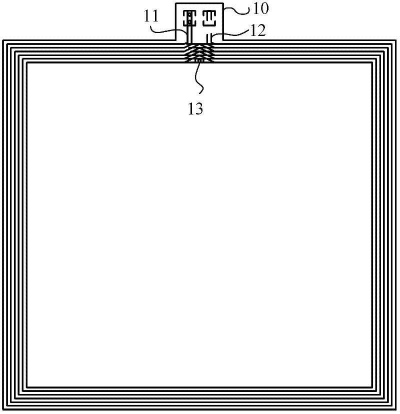
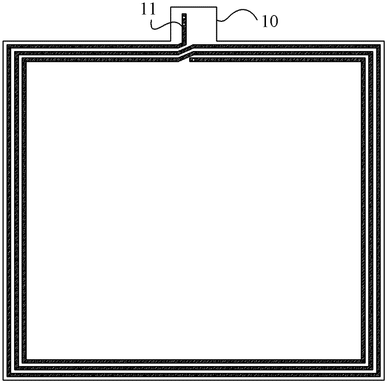
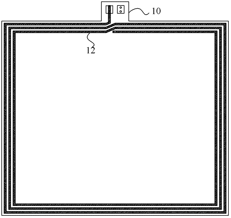
[0021] The NFC antenna of this embodiment includes: a substrate, a first coil and a second coil, the first coil is placed on the basic front side, the second coil is placed on the back side of the substrate, and one end of the first coil is used to connect to the antenna matching circuit. The other end of the feed end is connected to one end of the second coil, and the end of the second coil not connected to the first coil also leads to a feed end for connecting to the antenna matching circuit.

[0022] The substrate may be a flexible circuit board (FPC), the first coil and the second coil are placed on both sides of the FPC, the first coil and the second coil have the same winding direction, and two coils of the same winding direction are formed on both sides of the FPC.

[0023] One end of the first coil and the second coil are overlapped, and are connected through a copper-clad through hole at the overlapped position to form a complete NFC antenna coil loop, and the other en...


PUM


Abstract

The invention discloses a near field communication (NFC) antenna and terminal equipment. The NFC antenna comprises a substrate, a first coil and a second coil, wherein the first coil is arranged on the front surface of the substrate, the second coil is arranged on the back surface of the substrate, a feed end which is used for connecting with an antenna matching circuit is led out from one end of the first coil, the other end of the first coil is connected with one end of the second coil, and a feed end which is used for connecting with the antenna matching circuit is led out from the other end of the second coil which is not connected with the first coil. The NFC antenna and the terminal equipment have the advantages that the area of the NFC antenna can be effectively utilized; and on the premise that the total area (outer contour) of the NFC antenna is unchanged, the total antenna width is reduced, the coil turns and the effective area of the antenna are increased at the same time, the induced magnetic field intensity is enhanced, the induced electromotive force is improved and the antenna performance is improved.

Description

technical field [0001] The invention relates to the technical field of wireless mobile communication, in particular to a short-distance wireless communication antenna and terminal equipment. Background technique [0002] NFC (Near Field Communication) is a short-range non-contact communication technology, which combines non-contact sensing and wireless connection technology, and works in the 13.56MHz frequency band. Compared with other short-distance wireless communication technologies, NFC technology has the advantages of safer data transmission and faster response time, and is very suitable for micropayment, identity authentication and other fields in the wireless transmission environment. [0003] Since the working frequency band of NFC technology is 13.56MHz, the NFC antenna is required to have a large area, but due to the structural design of the terminal equipment, the available space of the NFC antenna is often limited, including the outer contour of the antenna and t...

Claims


Application Information

Patent Timeline
IPC IPC(8): H01Q1/38H01Q1/22
Inventor 文园
Owner ZTE CORP
Learn More