
Method for implementing flexible combined overload control for aircraft in large airspace

An overload control and aircraft technology, applied in attitude control, general control system, control/adjustment system, etc., can solve the problems of increasing the manufacturing cost of the aircraft control system, the angle of attack cannot respond, and the angular accelerometer is easily affected by interference signals.

Inactive Publication Date: 2012-08-22
NAVAL AERONAUTICAL & ASTRONAUTICAL UNIV PLA
View PDF0 Cites 35 Cited by
  • Summary
  • Abstract
  • Description
  • Claims
  • Application Information

AI Technical Summary

Problems solved by technology

[0004] classic The overload control method is not suitable for orbit change in large airspace. In addition, the response speed of overload to its command is much slower than the response speed of angular velocity to its command, so this control method has the disadvantage of slow response speed;
[0005] The overload control method needs to measure the angle of attack, so it is necessary to install an angle of attack sensor, which increases the manufacturing cost of the control system
Many aircraft cannot be installed with angle-of-attack sensors due to limited conditions, and when there is wind interference, the calculated angle of attack cannot reflect the real angle of attack, that is, the calculation is inaccurate. Therefore, the processing method of measuring the angle of attack is widely used in engineering applications. There are major defects;
[0006] Overload control method, angular acceleration It is the second order derivative of the attitude angle. Accurately measuring the signal requires a high sensitivity of the angular accelerometer; the angular accelerometer is easily affected by the interference signal. When the interference signal is large or the missile is flying with a large maneuver accurate; therefore, The overload control method also has limitations in engineering applications;
[0007] The overload control method needs to measure the angular acceleration signal, and the measurement of the angular acceleration signal is very inaccurate, and there are limitations in engineering applications; in addition, the method requires a large number of measuring devices, which increases the manufacturing cost of the aircraft control system

Method used


Image

  • Method for implementing flexible combined overload control for aircraft in large airspace
  • Method for implementing flexible combined overload control for aircraft in large airspace
  • Method for implementing flexible combined overload control for aircraft in large airspace

Examples


Embodiment Construction

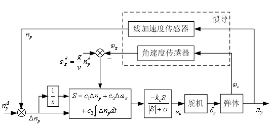
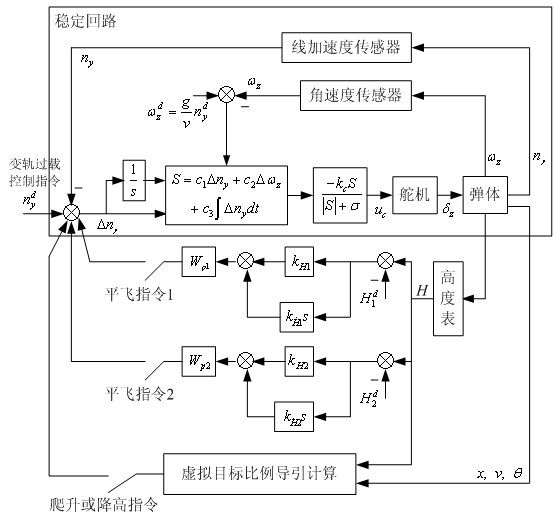
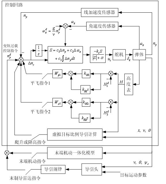
[0059] attached by figure 1 It can be seen that there are 6 design parameters for the entire pitch channel stabilization loop: , , , , and . 10-12 feature points can be selected for the entire flight of the aircraft. For each feature point, the design formula refers to the above formulas (1) to (15), and the calculation sequence is as follows.

[0060] According to formula (5) to get , ,and choice as long as the guarantee tends to zero as soon as possible, and the formula (5) guarantees that , that is, to ensure that the zero dynamics after reconstruction is asymptotically stable, and to ensure that the missile has an asymptotically stable positive angle of attack in level flight;

[0061] According to (6) and (7), calculate and ;

[0062] Calculate the reconstruction model parameters according to (8), (9) and (10) respectively , , , , and ;

[0063] Calculated according to (14) and (15) .

[0064] In the above calculation, only param...


PUM


Abstract

The invention discloses a method for implementing flexible combined overload control for an aircraft in a large airspace. A combined measured value of an inertial navigation linear accelerometer and an angular speed meter is adopted as a control value, the technical difficulty in realizing overload control of a non-minimum phase system is solved by means of reconstructing a mathematical equation, asymptotic stability of an attach angle and a sideslip angle in a whole flying journey is completely realized, and the method is applicable to flexible small-space non-planar flying control for supersonic aircrafts with large-space variable trajectories. The method for implementing combined overload control has the advantages of intuitive structure, simple design and capability of completely meeting engineering application requirements.

Description

technical field [0001] The invention relates to a combined overload control method for an aircraft to realize maneuvering in a large airspace, which belongs to the technical field of supersonic aircraft control, and is suitable for an aircraft to realize a large airspace (height 0-25 kilometers, lateral km) orbit change, small airspace non-planar maneuvers (spiral, pendulum, snaking and various combinations of maneuvers) flight control. The invention is simple in structure, and only uses two kinds of sensors of inertial navigation and altimeter to complete the task. In order to meet the working requirements of the engine, its attack angle and side slip angle can be controlled within 6° according to different ranges. Background technique [0002] Pure overload control cannot be applied to the control of the aircraft, because it is a non-minimum phase system, that is, it cannot solve the problem of attitude angle stability. The classic inner and outer loop overload control ...

Claims


Application Information

Patent Timeline
IPC IPC(8): G05D1/08G05B17/02
Inventor 顾文锦赵红超雷军委陈洁杨智勇
Owner NAVAL AERONAUTICAL & ASTRONAUTICAL UNIV PLA
Learn More