Cursor displayed float-type liquidometer

Inactive Publication Date: 2012-08-22
DALIAN JIAXIN ELECTROMECHANICAL INSTR CO TD
View PDF6 Cites 15 Cited by
  • Summary
  • Abstract
  • Description
  • Claims
  • Application Information

AI Technical Summary

Problems solved by technology

But it has the following disadvantages: both the float and the vernier are sliding friction, resulting in a large friction coefficient, which makes the friction force large and affects the accuracy and sensitivity, and is even unusable
Its disadvantages are: 1. The float is a sliding friction, and its disadvantages are also the same as above
2. The arrangement of magnetic steel in the entire circle of the float increases the weight of the float, which will inevitably increase the volume of the float
3. The demagnetization temperature of the magnetic steel limits the service temperature of the liquid level gauge
In addition, there is also the problem that the two guide rails need to be parallel and perpendicular to the ground at the same time, which increases the difficulty and cost of manufacturing

Method used


Image

  • Cursor displayed float-type liquidometer
  • Cursor displayed float-type liquidometer
  • Cursor displayed float-type liquidometer

Examples


Embodiment 1

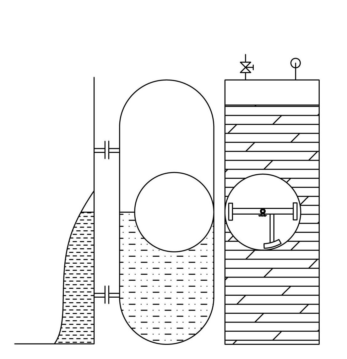
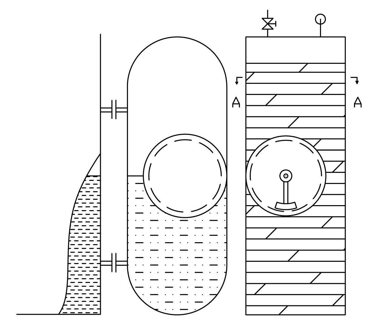
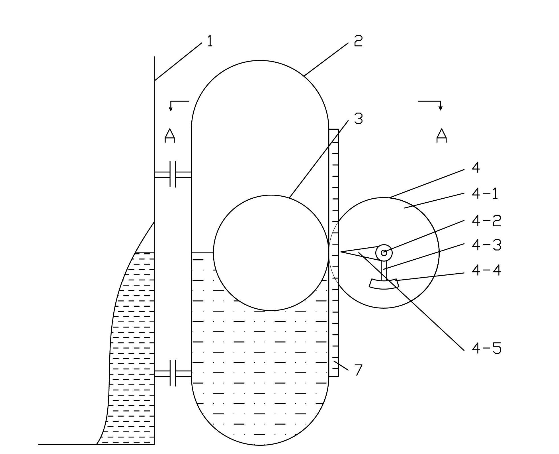
[0059] A float type liquid level gauge displayed by a vernier, such as image 3 , 4 As shown, it includes a float chamber 2 of non-ferromagnetic material and a float 3 therein, a vernier system 4 and a scale 7; the float 3 is a hollow sphere made of a ferromagnetic material, and the vernier 4 includes a central axis Cylindrical magnetic steel 4-1 with a hole, short shaft 4-2, connecting rod 4-3, the central hole of the magnetic steel is located on the axis of the magnetic steel and is horizontal, and the magnetic poles of the magnetic steel are distributed along the axial direction or Located on the inner and outer surfaces of its radial direction; the short shaft 4-2 passes through the central hole of the magnetic steel and is fixedly installed, and the two ends of the short shaft extend out of the magnetic steel 4-1, and the protruding parts at both ends are respectively equipped with The connecting xuan 4-3 rotating around the axis, the lower ends of the two connecting xua...

Embodiment 2

[0064] In order to prevent the use from being affected by rain, snow, ice, dust, etc., a vernier chamber 6 made of transparent material can be set on the basis of embodiment 1, and the above-mentioned vernier 4 is loaded into it. The vernier chamber 6 is adjacent to the float chamber 2. settings such as Figure 5 and Figure 6 shown.

[0065] The two magnetic coupling parts are always looking for the shortest distance to be coupled together, therefore, the buoy 3 and the vernier 4 always move up and down synchronously with the shortest distance. That is: under normal circumstances, the two will not deviate. That is to say the vernier can not break away from the plane 5 outside the float chamber 2 which is parallel to the axis of the float chamber 2 .

Embodiment 3

[0067] A float type liquid level gauge, such as Figure 7 As shown, it is different from Embodiment 1 in that a pulley 8 is erected outside and above the float chamber 2, one end of the connecting rope or connecting belt 9 is connected with the vernier 4 through the fixing frame 4-6, and the other end is connected with the counterweight 10; The fixed frame 4-6 is clamped on both sides of the magnetic steel 4-1 and hinged with the short shaft 4-2.

[0068] When the float 3 is half immersed in the liquid to be tested, the gravity of the counterweight 10 minus the gravity of the vernier 4 is equal to the gravity of the float 3 minus the buoyancy force suffered by the float 3 when it is half immersed in the liquid to be tested. Thus, the counterweight 10 drives the vernier 4 to give the buoy 3 an upward lifting force and realize force balance.

[0069] When the liquid level rises and falls, the balance of this force is broken, and the vernier 4 and the counterweight 10 move up an...


PUM


Abstract

The invention relates to a cursor displayed float-type liquidometer. A float chamber of the cursor displayed float-type liquidometer is made of non-ferromagnetic materials, a float is a hollow ball-shaped float made of ferromagnetic materials, and a graduation ruler is installed outside the float chamber; a cursor comprises a cylindrical magnetic steel with a central hole, a short shaft, a connection rod and a balancing weight, wherein the central hole of the magnetic steel is horizontally located on the axis of the magnetic steel, and magnetic poles of the magnetic steel are distributed along the axial direction or located on the radial inner and outer surfaces of the magnetic steel; the short shaft penetrates through the central hole of the magnetic steel to be fixedly installed, and the connection rod is hinged to the short shaft and capable of rotating around the short shaft; the balancing weight is fixedly connected with the lower end of the connection rod, and the center of gravity of the cursor is guaranteed to be located on the medial axis of the cursor and below the horizontal central line of the magnetic steel; and the outer wall of the float chamber is provided with a plane which is parallel to the axis of the float chamber, and the magnetic steel is in line contact with the plane and rolls on the plane along the axial direction of the float chamber. The cursor displayed float-type liquidometer uses the cursor to replace a buoy and is simple in structure, easy to manufacture, reliable in using, cost-saving and wide in application range.

Description

technical field [0001] The invention relates to the field of liquid level measurement, in particular to a float type liquid level gauge displayed by a vernier. Background technique [0002] The existing on-site indicating liquid level instruments include glass plate type, magnetic flap (column) type, buoy type, two-color water level gauge, etc. The glass plate type can only be visually inspected at a close distance, and it is difficult to visually inspect after being covered with dust, and the pressure resistance is limited. The magnetic flap (column) structure is relatively complex and prone to garbled characters. The applicable medium range of the two-color water level gauge is narrow and the pressure resistance is also limited. The glass plate type is also easily polluted by water quality, making visual inspection difficult. In addition, the glass plate type liquid level gauge or the two-color water level gauge cannot be used for heat preservation, resulting in high en...

Claims


Application Information

Patent Timeline
IPC IPC(8): G01F23/72
Inventor 范广会王嘉贤
Owner DALIAN JIAXIN ELECTROMECHANICAL INSTR CO TD
Why Eureka
Try Eureka