Electric control system and method for cooling fan of automobile engine

A technology of electronic control system and automobile engine, applied in the direction of engine cooling, coolant flow control, engine components, etc., can solve problems such as difficulty in application of products, inability to meet special support, and inability of designers to fully grasp functional resources.

Inactive Publication Date: 2012-08-22
SOUTH CHINA UNIV OF TECH
View PDF6 Cites 13 Cited by
  • Summary
  • Abstract
  • Description
  • Claims
  • Application Information

AI Technical Summary

Problems solved by technology

[0005] The core of the third control mode controller lies in the ECU. The single-chip microcomputer components currently relied on in domestic ECU technology generally use products from foreign companies such as Freescale, Infineon, and Intel, and foreign suppliers provide their own products. The complete set of technical services makes it difficult for the products of domestic ECU service providers to be applied
At the same time, the hardware provided by the supplier is bound to its own software, and the designer cannot fully grasp its functional resources, and the scalability of the hardware, such as the number of interfaces, cannot meet the needs of special support

Method used


Image

  • Electric control system and method for cooling fan of automobile engine
  • Electric control system and method for cooling fan of automobile engine
  • Electric control system and method for cooling fan of automobile engine

Examples


Embodiment Construction

[0039] The present invention will be further described below in conjunction with the accompanying drawings and embodiments, but it should be noted that the protection scope of the invention is not limited to the scope described in the embodiments.

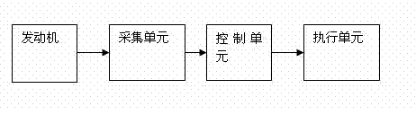
[0040] as attached figure 1 Shown: a kind of automobile engine cooling fan control system of the present invention, this system comprises

[0041] The collection unit is used to collect various parameters of the engine and transmit the various parameters of the engine to the control unit;

[0042] The control unit, including DSP, is used to calculate the target speed of the fan according to various parameters of the engine, and obtain the PWM pulse width signal for driving the execution unit;

[0043] The execution unit includes a fan motor connected to each other, a fan, an isolation circuit of the fan, and a high-power H-bridge drive circuit, and drives the fan motor according to the PWM pulse width signal to make the fa...


PUM


Abstract

The invention discloses an electric control system and a method for a cooling fan of an automobile engine. The electric control system comprises an acquisition unit, a control unit and an execution unit, wherein the acquisition unit is used for acquiring various engine parameters in real time; the engine parameters comprise inlet and outlet temperatures of cooling water; the control unit is used for calculating the target rotating speed of a fan according to various parameters of the engine and obtaining a PWM (Pulse-Width Modulation) pulse-width signal for driving the execution unit; and the execution unit is used for driving a fan motor according to the PWM pulse-width signal to enable the fan to reach the target rotating speed. According to the electric control system and method disclosed by the invention, intelligent control over the rotating speed of the cooling fan is realized, so that the situation that a cooling system of the engine works under optimal work conditions is realized and the dynamic property of the engine is exerted with minimum energy consumption; the economy is realized; and the emission requirement is met.

Description

technical field [0001] The invention relates to the field of automotive electronic control, in particular to an electronic control system and method for an automotive engine cooling fan. Background technique [0002] The most commonly used cooling system for automobile engines is liquid cooling. That is, the liquid used for cooling passes through the circulation system, and then dissipates heat through the radiator to cool down the engine. The cooling fan is used to force the radiator to make up air through the wind speed to meet the needs of moderate cooling of the engine. [0003] From the perspective of the working form of the cooling fan, there are three control methods for the cooling fan: one is the mechanical drive control method suitable for large vehicles and heavy vehicles; the other is the self-controlled electric control method that has nothing to do with the engine ECU and monitors the environmental parameters independently; It is a comprehensive intelligent c...

Claims


Application Information

Patent Timeline
IPC IPC(8): F01P7/04
Inventor 黄旭为王惜慧郭明林雷雄
Owner SOUTH CHINA UNIV OF TECH
Why Eureka
Try Eureka