
Unloading control method for steel structure temporary bracing

A temporary support and control method technology, applied in building construction, building maintenance, construction, etc., can solve the problems of inconvenient operation for on-site unloading workers, inability to measure in real time, difficulty in ensuring safety, etc., and achieve intuitive and specific measurement and convenient operation , high precision effect

Inactive Publication Date: 2012-08-22
SHANGHAI CONSTRUCTION GROUP +1
View PDF2 Cites 15 Cited by
  • Summary
  • Abstract
  • Description
  • Claims
  • Application Information

AI Technical Summary

Problems solved by technology

[0005] (1) It is difficult to measure. Although the absolute displacement of key points can be measured by measuring instruments (such as total station and level), when unloading complex temporary supports, the absolute displacement of key points is not always downward, but It is possible to go upwards, such as the steel shell of the National Grand Theater; and the reaction force of the jack is used as a control variable, which cannot be measured in real time on site
[0006] (2) The operation is inconvenient. Whether it is the absolute displacement or the jack reaction force as the control variable, it is not convenient for the on-site unloading workers to operate
[0007] (3) It cannot be compared with the calculation results of simulation analysis in real time, it is difficult to control, and it is difficult to guarantee safety

Method used


Image

  • Unloading control method for steel structure temporary bracing
  • Unloading control method for steel structure temporary bracing
  • Unloading control method for steel structure temporary bracing

Examples


Embodiment Construction

[0027] The method for controlling the unloading of the temporary support of the steel structure of the present invention will be further described in detail below.

[0028] The invention will now be described in more detail with reference to the accompanying drawings, in which preferred embodiments of the invention are shown, it being understood that those skilled in the art may modify the invention described herein and still achieve the advantageous effects of the invention. Therefore, the following description should be understood as the broad knowledge of those skilled in the art, but not as a limitation of the present invention.

[0029] In the interest of clarity, not all features of an actual implementation are described. In the following description, well-known functions and constructions are not described in detail since they would obscure the invention with unnecessary detail. It should be appreciated that in the development of any actual embodiment, numerous impleme...


PUM


Abstract

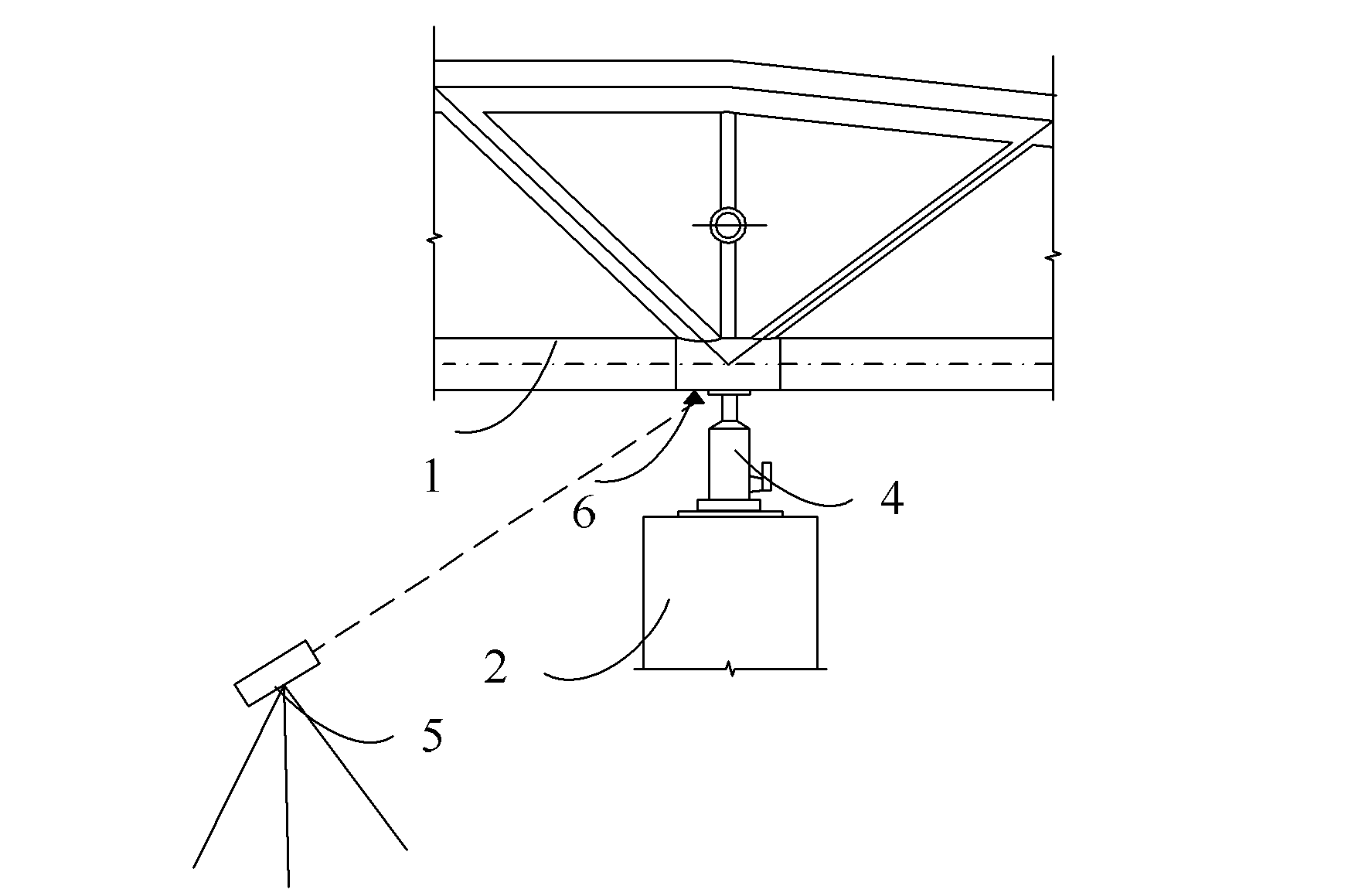
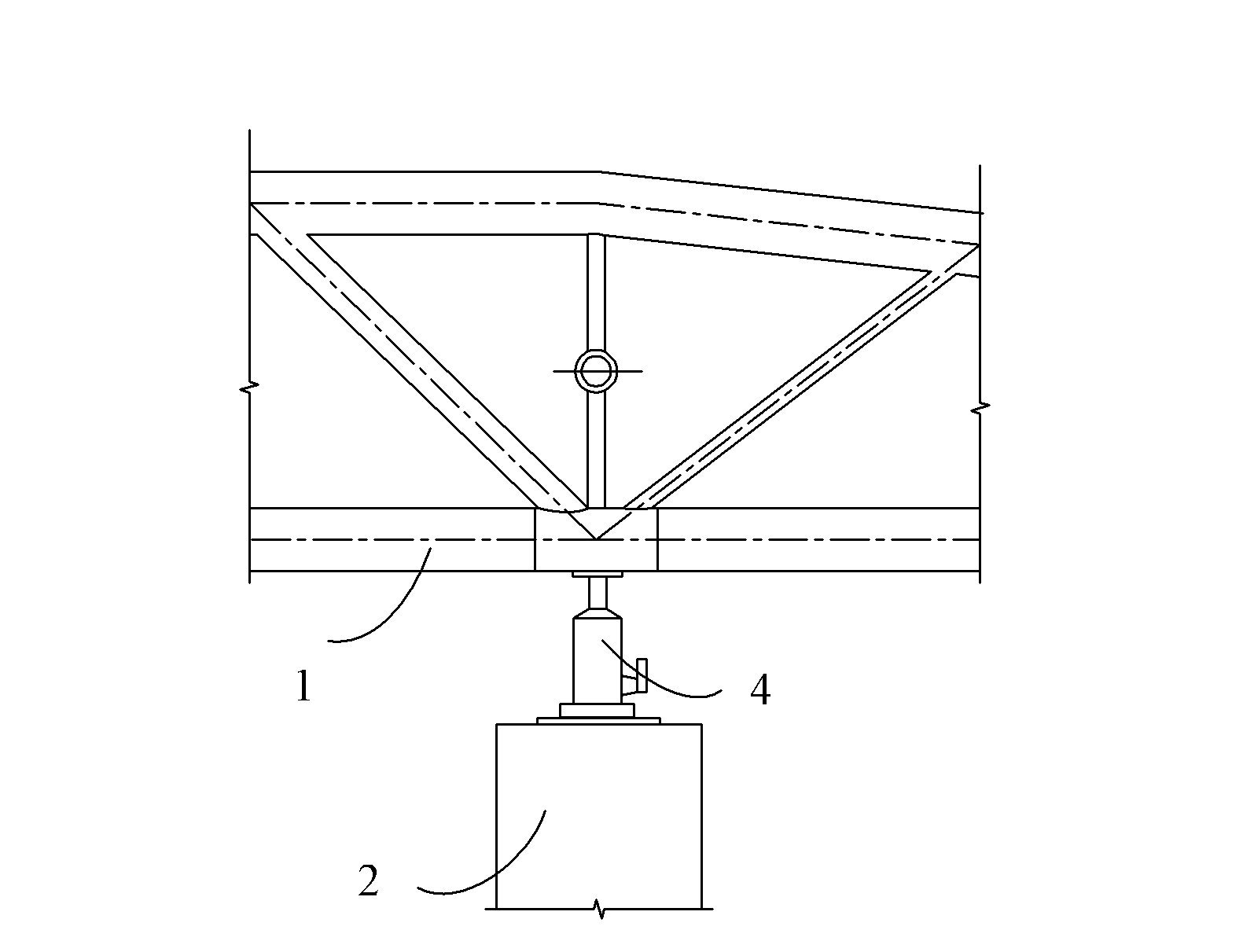
Disclosed is an unloading control method for steel structure temporary bracing. The method comprises that simulation analysis of an overall construction process of an integral structure is performed, so that unloading quantities of various bracing points on a temporary bracing structure are determined, the integral structure comprises a main structure and the temporary bracing structure, and jacks are respectively arranged at positions of the bracing points on the temporary bracing structure for supporting the main structure; unloading is performed through adjustment of routes of the jacks; route changes of the jacks are measured based on the unloading quantities determined by the simulation analysis, so that the routes of the jacks are in accordance with the unloading quantities of corresponding bracing points determined by the simulation analysis; and the next step of unloading is performed in the same way, and finally synchronous unloading is achieved through grading sorted unloading. The unloading control method has the advantages that the routes of the jacks are used as control variables in unloading construction of the steel structure temporary bracing, the unloading quantities can be controlled accurately, real-time measurement is performed conveniently, the accuracy is high, the safety is guaranteed, and the like.

Description

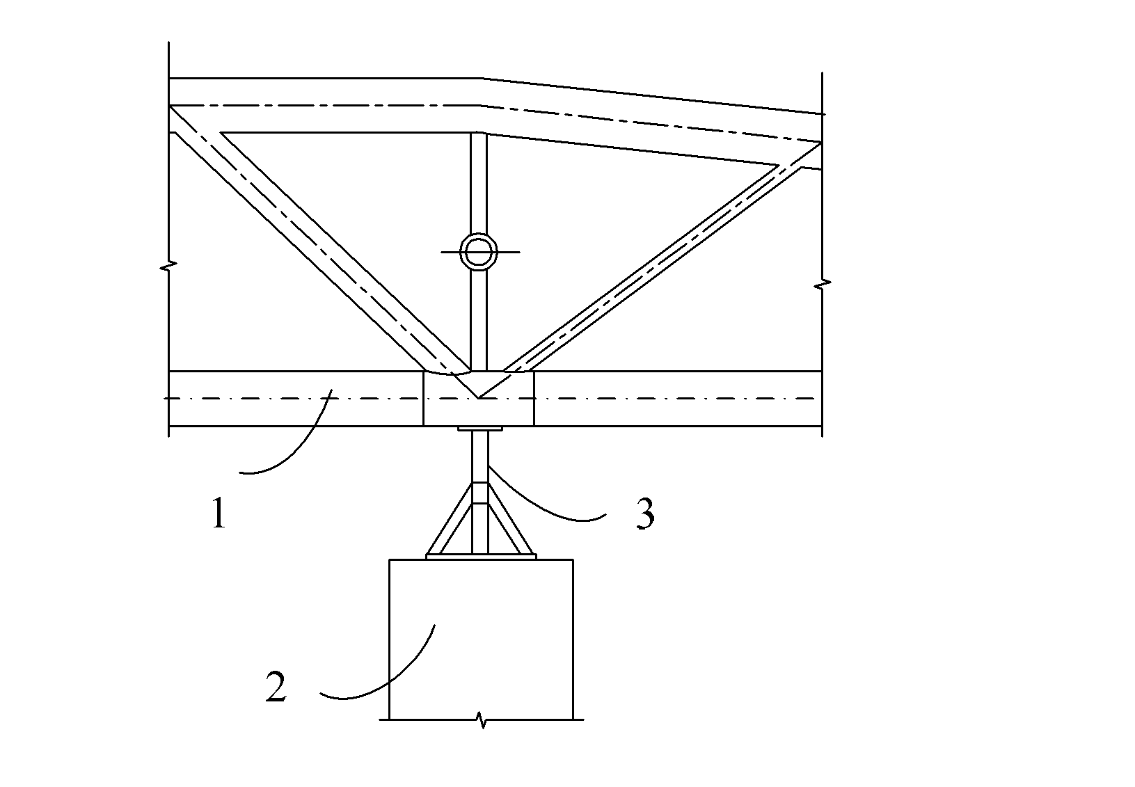
technical field [0001] The invention relates to the technical field of steel structure construction, in particular to a method for controlling unloading of temporary supports of steel structures. Background technique [0002] The unloading technology of temporary supports for steel structures is a key technology in the construction process of steel structures. Whether the implementation of the unloading scheme is reasonable is related to the safety of the main structure and the temporary structure and the quality of the main structure. A reasonable unloading method not only ensures the safety of the structure, but also is simple and easy to operate implement. [0003] The control variable of unloading is the key of unloading technology, and the existing temporary support unloading device and method all take the absolute displacement of key points on the main structure or the reaction force of the jack as the control variable. see figure 1 and figure 2 , figure 1 Schemat...

Claims


Application Information

Patent Timeline
Patent Type & Authority Applications(China)
IPC IPC(8): E04G23/08
Inventor 伍小平李鑫奎高振锋陈晓明王云飞
Owner SHANGHAI CONSTRUCTION GROUP
Learn More