
Plastic container, long flow member and coating apparatus

A technology for a plastic container and a flow path member is applied in the fields of plastic containers, elongated flow path members and coating devices, and can solve problems such as inability to carry out viscous liquid and pollution.

Active Publication Date: 2012-08-22
CEMEDAINE CO LTD
View PDF10 Cites 10 Cited by
  • Summary
  • Abstract
  • Description
  • Claims
  • Application Information

AI Technical Summary

Problems solved by technology

In the device of Patent Document 2, since the suction hose 6 is repeatedly used, the suction hose 6 is taken out with the viscous liquid attached to the front end portion at the end of the liquid feeding process, so the same disadvantages as in Patent Document 1 occur. That is, these adhered viscous liquids (water-based paint in Patent Document 2) splash around the coating device to cause contamination, and since the suction port of the suction hose 6 is formed at the front end of the suction hose 6, it is also There is a disadvantage that when the suction port is blocked due to contact with the wall of the inner container 1, etc., an accident may occur that the suction of the viscous liquid cannot be performed.

Method used


Image

  • Plastic container, long flow member and coating apparatus
  • Plastic container, long flow member and coating apparatus
  • Plastic container, long flow member and coating apparatus

Examples


Embodiment Construction

[0077] Below, refer to Figure 1 to Figure 23 and Figure 28 ~ Figure 42 Embodiments of the present invention will be described, but these are merely illustrative, and it goes without saying that various modifications can be made without departing from the technical idea of ​​the present invention.

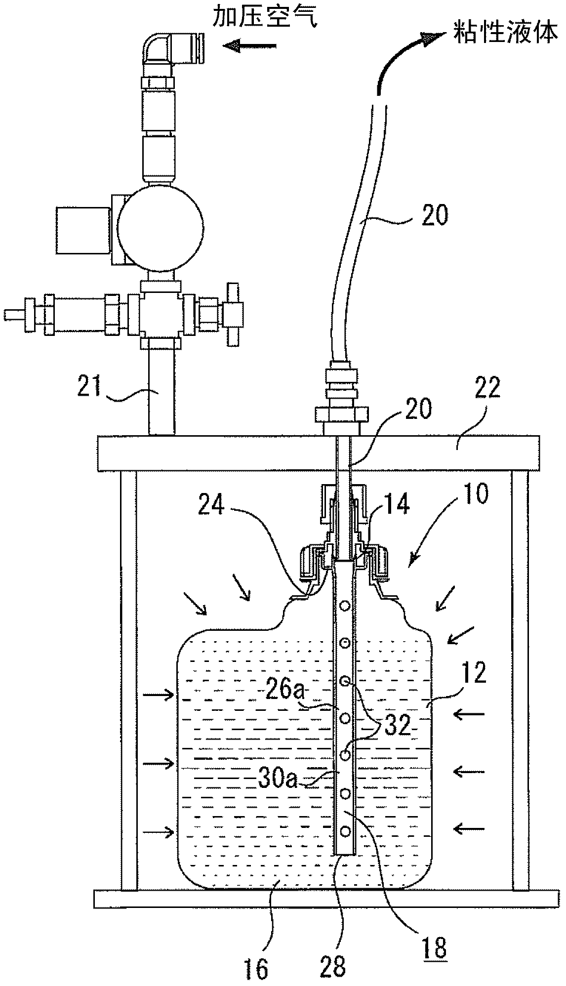
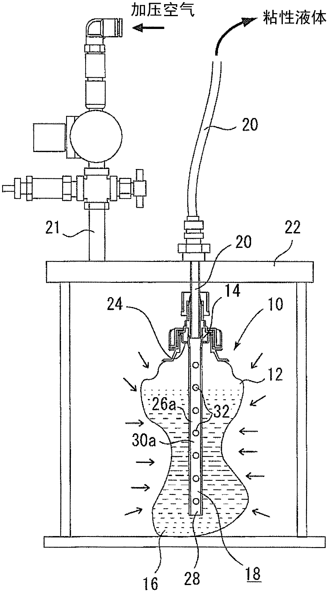
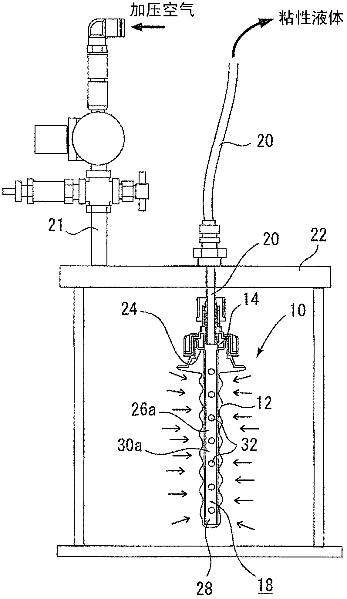
[0078] figure 1 It is a cross-sectional explanatory view showing an embodiment in which the plastic container of the present invention is installed inside a pressurized tank, and shows a state in which a viscous liquid is filled in the plastic container body. exist figure 1 In , the symbol 10 represents the plastic container of the present invention, which has a plastic container main body 12 . The plastic container main body 12 is formed of a flexible plastic material that can be crushed due to pressure, such as polyethylene or polypropylene (polypropylene), and soft polypropylene is particularly preferred in terms of flexibility, economy, and ease of forming. vinyl. An op...


PUM


Abstract

The invention discloses a plastic container, a long flow member and a coating apparatus, being able to avoid the harmful condition that the flow path of the viscous liquid is closed when the plastic container body is shriveled, and to eliminate the condition that the viscous construction member adhered to the pipe when the pipe is repeatedly used so as to pollute the surrounding. The plastic container comprises a plastic container body which is provided with an opening and is filled with the viscous liquid and has flexibility so as to help the viscous liquid ejected from the opening when the container is shriveled by compression, a long flow member which extends to the inside of the plastic container body and arranged at the opening, wherein the ejection flow path at least beginning with the side surface formed when the viscous liquid is ejected is taken as the ejection flow path of the viscous liquid; and when the plastic container body is shriveled by compression, the shriveled plastic container and the long flow member can be deprecated together.

Description

technical field [0001] The present invention relates to a plastic container, an elongated flow path member, an applicator, a cap with an inner plug, a plastic container in a sealed state, and a plastic container in a bundled state, which are effectively used in the following cases. A viscous liquid, especially a moisture-curable adhesive curable composition or an oxygen-curable adhesive curable composition is stored in a flexible bag or container, and the pressure is applied from the outside to make the viscous liquid The bag or container deforms and shrinks, and the viscous liquid inside is discharged to the outside for coating. Background technique [0002] Conventionally, in coating devices for applying moisture-curable adhesives or oxygen-curable adhesives, since the adhesive solidifies when in contact with the air, when the adhesive splashes, it will be directly cured at the splashed part and cause damage. Contamination and other disadvantages are caused, so it is nece...

Claims


Application Information

Patent Timeline
IPC IPC(8): B05C11/11B05C11/10B05C5/00
CPCB05C5/02B05C11/11B65D41/0407B65D47/42B65D81/18
Inventor 冈村直实斋藤敦渡边担
Owner CEMEDAINE CO LTD
Learn More