
A Circularly Polarized Microstrip Antenna Realizing Wide Beam

A microstrip antenna and circular polarization technology, applied in the field of electromagnetic waves, can solve the problems that wide-angle scanning phased array antennas cannot be widely used, and the microstrip antenna has narrow lobe width, so as to reduce the side lobe level and widen the lobe The effect of width and convenient processing

Inactive Publication Date: 2015-08-19
UNIV OF ELECTRONICS SCI & TECH OF CHINA
View PDF4 Cites 0 Cited by
  • Summary
  • Abstract
  • Description
  • Claims
  • Application Information

AI Technical Summary

Problems solved by technology

However, the narrow lobe width of the microstrip antenna has become the main disadvantage that limits its wide application to wide-angle scanning phased array antennas.

Method used


Image

  • A Circularly Polarized Microstrip Antenna Realizing Wide Beam
  • A Circularly Polarized Microstrip Antenna Realizing Wide Beam
  • A Circularly Polarized Microstrip Antenna Realizing Wide Beam

Examples


Embodiment Construction

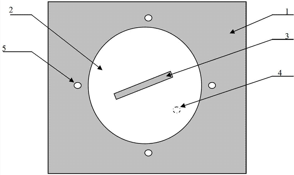
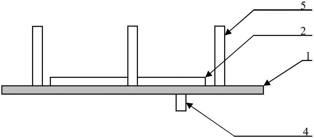
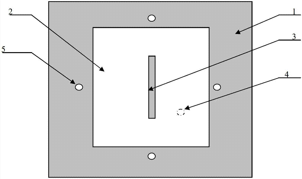
[0016] Such as figure 1 As shown, the wide-beam circularly polarized microstrip antenna includes a dielectric substrate 1, a short-circuit column 5, a circular microstrip patch 2, a patch slit 3 for realizing circular polarization, a feed coaxial connector 4, and a circular Shaped microstrip patch 2 and short-circuit column 5 are arranged on one side of dielectric substrate 1, and feed coaxial joint 4 is arranged on the other side of dielectric substrate 1, such as figure 2 shown. There are slits 3 in the circular microstrip patch 2, and four short-circuit columns are evenly arranged in the axisymmetric direction of the circular microstrip patch 2 and adjacent to the edge of the circularly polarized microstrip patch. Of course, more than 4 even-numbered short-circuit columns can also be used as long as they are evenly distributed on the edge of the circular microstrip patch. There are slits on the patch, and circular polarization is achieved by forming two orthogonal modes....


PUM


Abstract

The invention provides a circularly-polarized microstrip antenna for realizing a wide beam. The circularly-polarized microstrip antenna comprises a dielectric substrate, a circularly-polarized microstrip patch and a coaxial feeder connector, wherein the circularly-polarized microstrip patch is arranged on one surface of the dielectric substrate, and the coaxial feeder connector is arranged on the other surface of the dielectric substrate; and the circularly-polarized microstrip antenna is characterized by also comprising four or more even number of short circuit columns, wherein the short circuit columns are uniformly arranged in the axisymmetric direction of the circularly-polarized microstrip patch and are adjacent to the edge of the circularly-polarized microstrip patch. A certain included angle is formed between the maximum radiation direction of the short circuit columns and the axial direction of a microstrip patch antenna; and through overlaying with a circularly-polarized radiation field of the microstrip patch antenna, the wide beam is achieved.

Description

technical field [0001] The invention relates to electromagnetic wave technology, in particular to wide-beam circularly polarized microstrip antenna technology. Background technique [0002] The phased array antenna has the advantages of fast scanning speed and high scanning accuracy. Since it was proposed, it has been highly valued and widely used in various airborne, shipborne, and vehicle-mounted phased array radars. In order to be able to detect targets within a wide angle, the phased array antenna is required to have wide-angle scanning characteristics. In order to reduce the side lobe level when the phased array antenna scans at a wide angle, the antenna unit is required to have a wide lobe pattern. Microstrip antennas have the advantages of small size, light weight, low processing cost, and easy integration with active devices. However, the narrow lobe width of the microstrip antenna has become the main disadvantage that limits its wide application to wide-angle scan...

Claims


Application Information

Patent Timeline
Patent Type & Authority Patents(China)
IPC IPC(8): H01Q13/08H01Q1/38
Inventor 杨峰吴川李岩王良翼杨鹏韩垒
Owner UNIV OF ELECTRONICS SCI & TECH OF CHINA
Learn More