
Erection method of indoor large-scale magnetic field generator

A magnetic field generator, a large-scale technology, applied in the fields of electromagnetism and material mechanics, can solve the problems of difficult maintenance, time-consuming, high cost, etc., and achieve the effect of fast construction speed, good structure roundness, and simple structure

Active Publication Date: 2012-08-15
THE THIRD ENG CORPS RES INST OF THE HEADQUARTERS OF GENERAL STAFF PLA
View PDF4 Cites 3 Cited by
  • Summary
  • Abstract
  • Description
  • Claims
  • Application Information

AI Technical Summary

Problems solved by technology

On the one hand, in order to form a uniform magnetic field in a large space inside the magnetic field coil to facilitate the placement of test pieces such as shielded room models, shielded shelters, and large electronic equipment, this puts forward requirements on the diameter of the magnetic field coil, and its construction is difficult; on the other hand On the one hand, in order to reduce the electromagnetic pollution of the environment caused by the magnetic field as much as possible, the magnetic field coil must be placed in an airtight shielding room, and the size of the shielding door is limited. It is unrealistic to make the magnetic field coil outdoors and then move it as a whole or install it indoors
A relatively direct method is to use insulating materials to build a drum with a diameter as large as the magnetic field coil in the shielding room, carve a helix on the outer wall of the drum as required, and then wind the magnetic field coil on the drum wall. The method is time-consuming, labor-intensive, expensive, inconvenient for specimen placement and experimental observation, and difficult to maintain

Method used


Image

  • Erection method of indoor large-scale magnetic field generator
  • Erection method of indoor large-scale magnetic field generator
  • Erection method of indoor large-scale magnetic field generator

Examples


Embodiment Construction

[0020] Specific embodiments of the present invention are described with reference to the accompanying drawings.

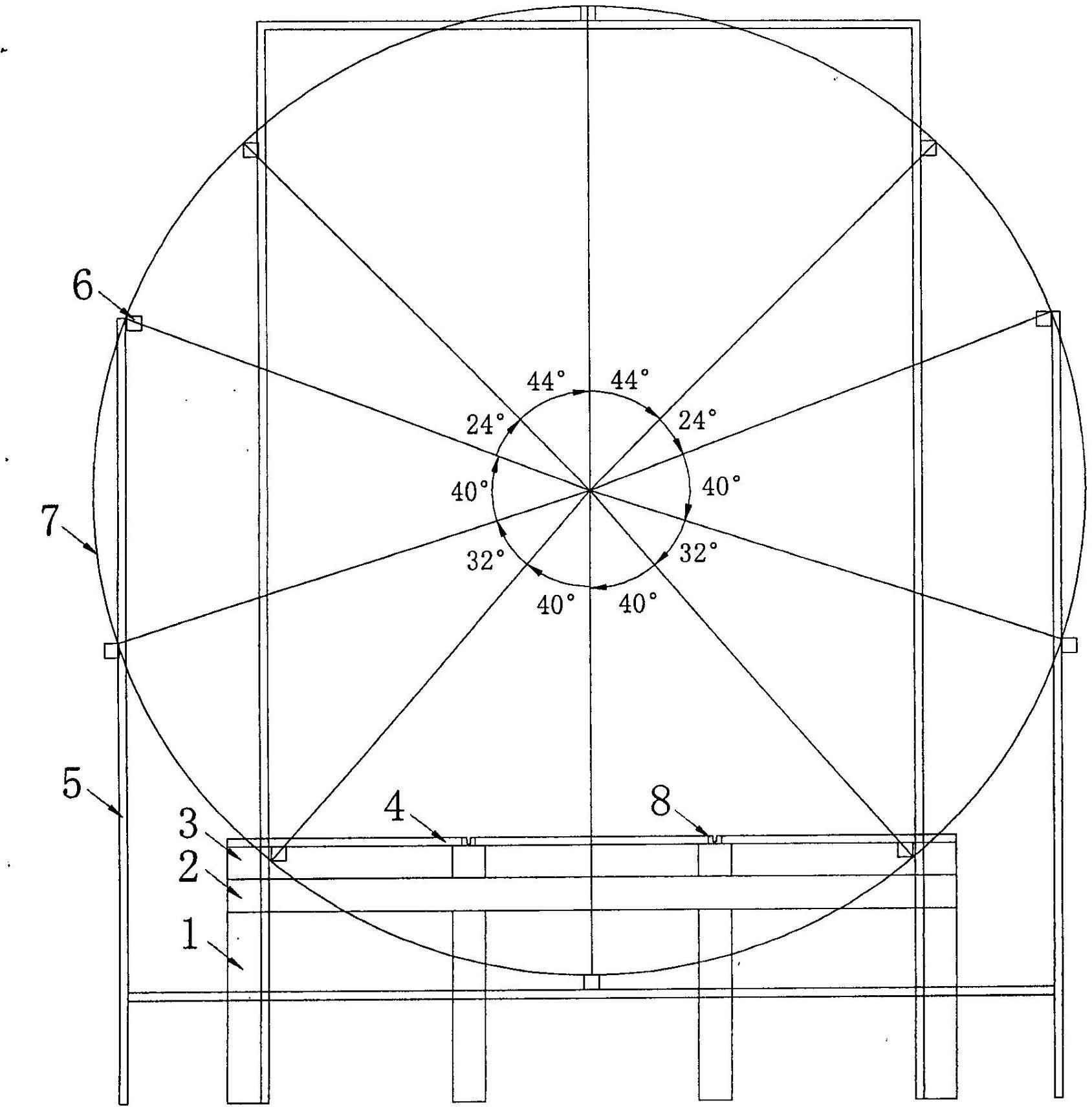
[0021] As shown in the accompanying drawings, the described large-scale magnetic field erection method includes the erection of the magnetic field coil support device and the winding of the magnetic field coil:

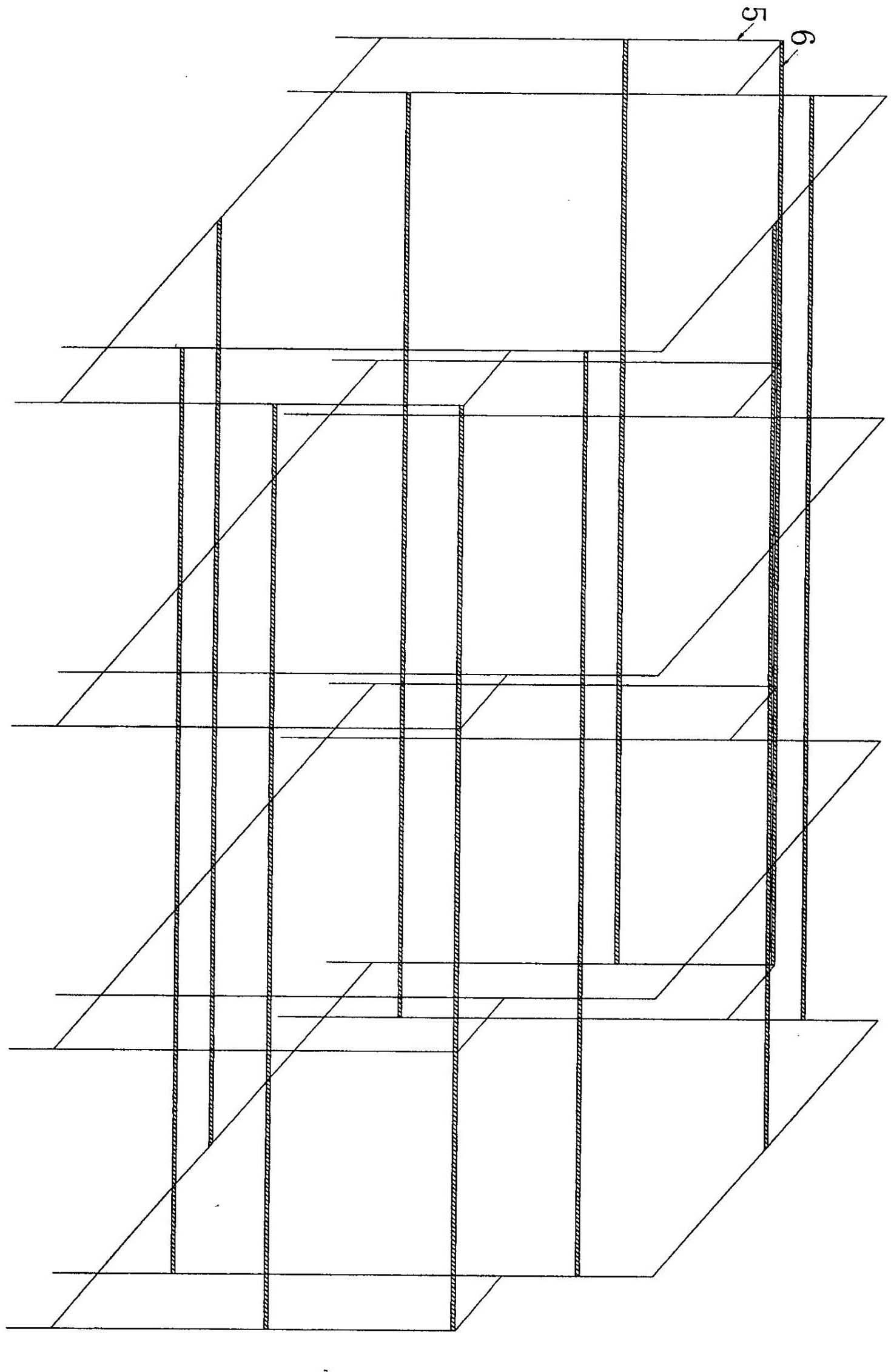
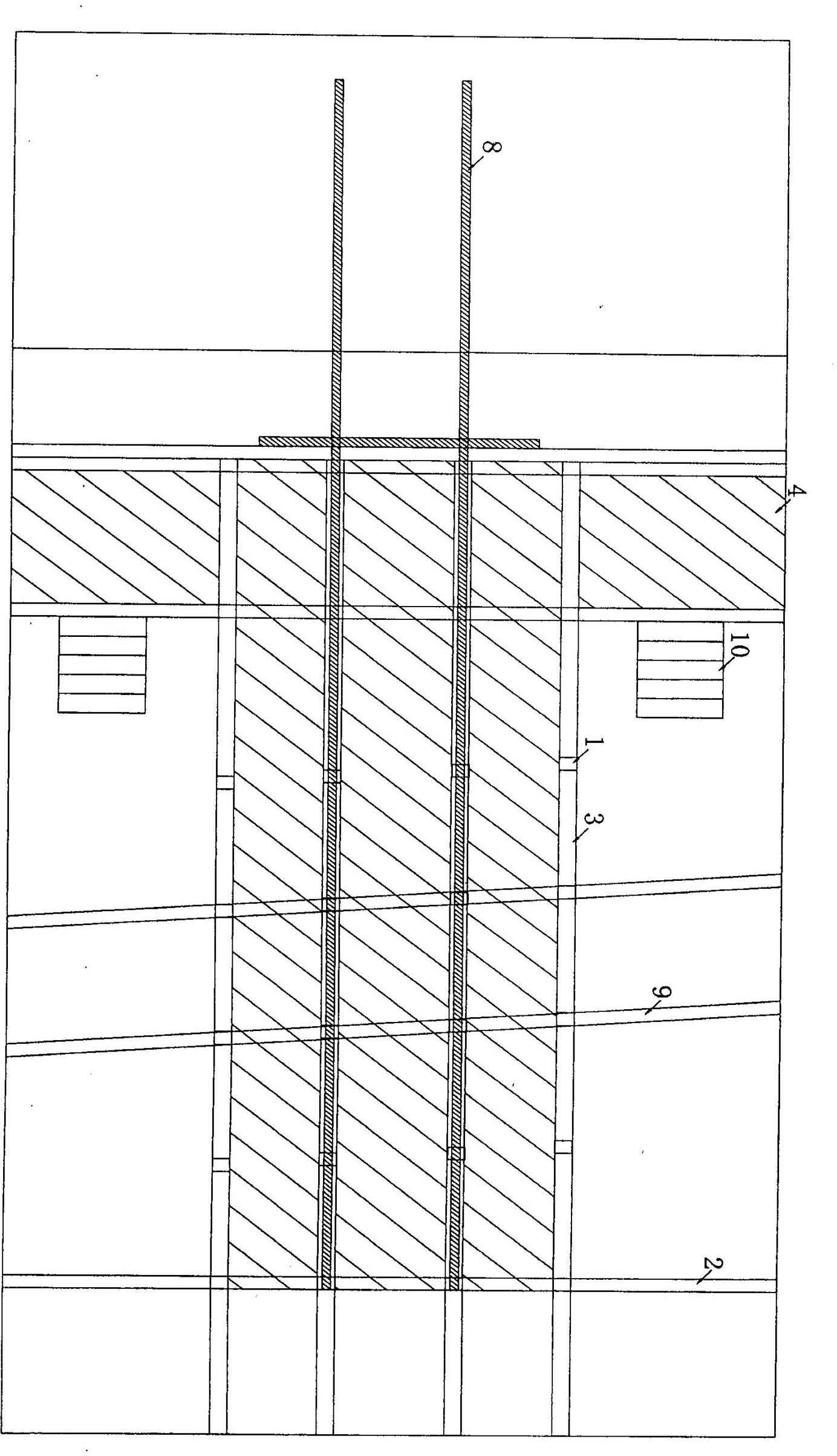
[0022] a: erection of the magnetic field coil support device: the magnetic field coil support device is set indoors, the magnetic field coil support device includes a magnetic field coil support mechanism and a test platform, and the test platform is located at the bottom of the support mechanism. The support mechanism consists of a set of vertical The straight magnetic field coil support frame 5 is connected and fixed with the scale bar 6 which is parallel to the axis of the magnetic field coil and tangent to the magnetic field coil. Each scale bar 6 has only one positioning scale groove with the single-turn magnetic field coil. The distance between adjac...


PUM


Abstract

The invention relates to an erection method of an indoor large-scale magnetic field generator. The erection method comprises erection of a magnetic field coil support device and winding of magnetic field coils, wherein the magnetic field coil support device is arranged indoor, the magnetic field coil support device comprises a magnetic field coil supporting mechanism and a testing platform, wherein the testing platform is positioned on the lower part of the supporting mechanism, and the supporting mechanism is formed by a group of vertical magnetic field coil supporting frames and magnetic field coil shaft lines which are parallel and scale strips which are tangent with the magnetic field coils are connected and fixed so as to form the supporting mechanism; the winding of the magnetic field magnetic field coils comprises: the magnetic field coil support device finishes erection, the accurate length of single-turn magnetic field coils is calculated and a copper pipe is cut according tothe diameter of each magnetic field coil and turn distance; and arc lengths corresponding to adjacent positioning scale grooves on scale strip are calculated along a clockwise direction, the copper pipe is fixed on the scale grooves in a clockwise manner according to the position of a fixed point, and a round magnetic field coil is basically formed after fixing.

Description

technical field [0001] The invention relates to the technical fields of electromagnetism, material mechanics, etc., in particular to an indoor large [0002] The erection method of the magnetic field generator is suitable for the erection needs of large indoor magnetic field coils. Background technique [0003] Large-scale magnetic field generators, especially indoor large-scale magnetic field generators, are experimental infrastructures rarely built in China at this stage. On the one hand, in order to form a uniform magnetic field in a large space inside the magnetic field coil to facilitate the placement of test pieces such as shielded room models, shielded shelters, and large electronic equipment, this puts forward requirements on the diameter of the magnetic field coil, and its construction is difficult; on the other hand On the one hand, in order to reduce the electromagnetic pollution of the environment caused by the magnetic field as much as possible, the magnetic fi...

Claims


Application Information

Patent Timeline
Patent Type & Authority Applications(China)
IPC IPC(8): H01F7/00H01F5/00G01R33/00
Inventor 李跃波何为刘锋杨杰潘征于浩黄刘宏张玉生
Owner THE THIRD ENG CORPS RES INST OF THE HEADQUARTERS OF GENERAL STAFF PLA
Learn More