
Improved Zernike moment edge detection method

An edge detection and edge direction technology, applied in the field of image processing, can solve the problems of large edge detection error and poor sub-pixel detection effect, and achieve the effect of compensating for large positioning errors

Inactive Publication Date: 2012-08-15
CHONGQING UNIV
View PDF3 Cites 22 Cited by
  • Summary
  • Abstract
  • Description
  • Claims
  • Application Information

AI Technical Summary

Problems solved by technology

The analysis found that the Zernike moment method proposed by Ghosal is based on straight line edges. When the detection target is a pixel near the intersection point, the algorithm treats the broken line edge in each template as a straight line, and the sub-pixel detection effect is poor.
[0004] Therefore, an improved Zernike moment edge detection algorithm is needed to solve the problem of large edge detection errors near the intersection when the Ghosal algorithm uses Zernike moments for sub-pixel edge detection

Method used


Image

  • Improved Zernike moment edge detection method
  • Improved Zernike moment edge detection method
  • Improved Zernike moment edge detection method

Examples


Embodiment 1

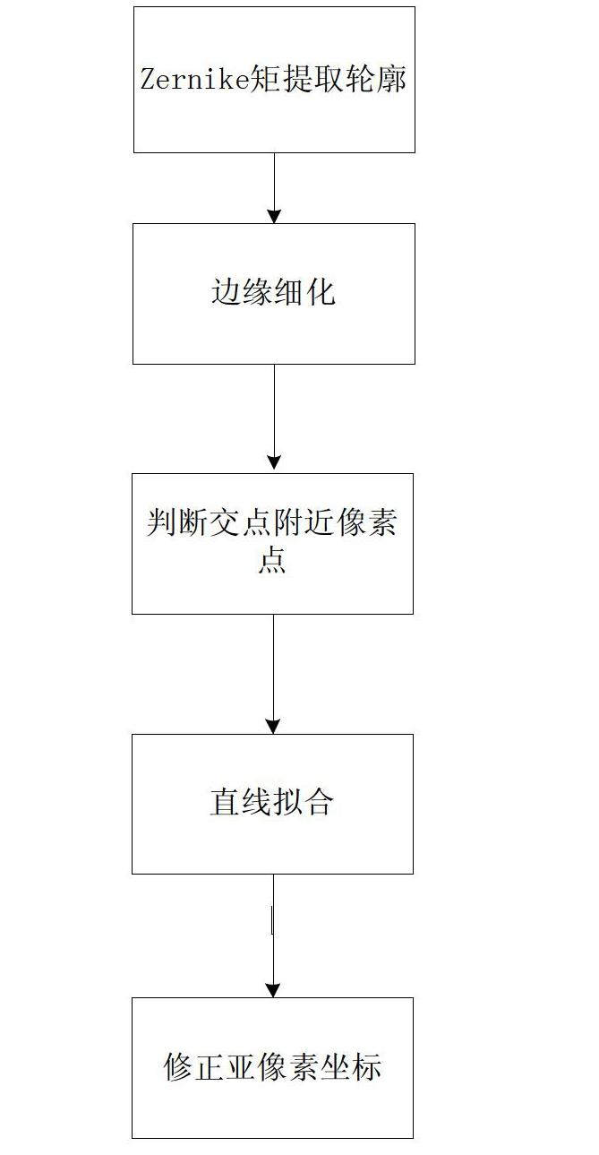
[0036] The improved Zernike moment edge detection method provided by the invention comprises the following steps:

[0037] 1) Acquire an image and extract the edge of the image; in this embodiment, the Zernike moment method is used to extract the edge of the image, and the image in this embodiment is an industrial CT image.

[0038] 2) Thinning the edge; the thinning edge in this embodiment is performed by suppressing the non-minimum value of the edge distance parameter l for each edge point in the image in the direction of the maximum gradient.

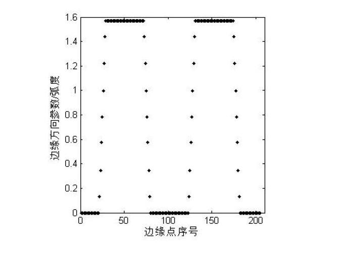
[0039] 3) Obtain the edge direction parameter φ distribution and the edge direction parameter difference value Δφ; this embodiment uses 8-chain code tracking to obtain the edge direction parameter φ distribution; this embodiment uses the following formula to calculate the direction of the edge direction parameter φ of the detected edge point Pre-difference value Δφ:

[0040] Δφ=φ(n+1)-φ(n), n=1,2,3...(NUM-1),

[0041] Among them, Δ...

Embodiment 2

[0049] Embodiment 2 provided by the present invention adopts the improved Zernike moment edge detection method in the following manner.

[0050] Step 1, the Zernike moment method extracts the edge contour, and the specific implementation steps of the Zernike moment sub-pixel edge detection are as follows:

[0051] (1) Calculation template Re[M 11 ], Im[M 11 ] and M 20 ;

[0052] where M pq Represents the p-order q-order Zernike moment template, M 11 Denotes a first-order linear Zernike moment template, M 20 Represents the second-order zero-order Zernike moment template, Re[M 11 ] for M 11 Template real part, Im[M 11 ] for M 11 Template imaginary part.

[0053] (2) Using the template Re[M 11 ], Im[M 11 ] respectively with the image convolution operation to obtain the corresponding Zernike moment real part Re[A 11 ], and the imaginary part Im[A 11 ], M 20 Convolved with the image to obtain the second-order zero-order Zernike moment A 20 . Zernike moment template...


PUM


Abstract

The invention discloses an improved Zernike moment edge detection method, which relates to an image processing method. The invention provides an improved Zernike moment edge detection method, which aims to the sub-pixel positioning of pixel points near an intersection point. The method comprises the following steps: carrying out sub-pixel edge extraction on an industrial CT (computed tomography) image by using a Zernike moment method, and refining an edge; then, obtaining the distribution of an edge direction parameter phi by using a 8-chain code tracing method, and calculating a difference value delta phi of the edge direction parameter phi; selecting a threshold T; judging whether an edge point is the pixel point near the intersection point; if the edge point is not the pixel point near the intersection point, carrying out least square fit on the edge point so as to obtain a linear equation; and calculating the sub-pixel coordinates of a to-be-corrected edge point near the intersection point by using the linear equation. The improved Zernike moment edge detection method well makes up for a shortage that the positioning error of a pixel point near an intersection point in a Ghosal algorithm is large, and has an important significance for high-precision area measurement and high-precision three-dimensional measurement.

Description

technical field [0001] The invention relates to an image processing method, in particular to an improved Zernike moment edge detection method for sub-pixel positioning of intersection points. Background technique [0002] Industrial CT (Industry Computerized Tomogragh) is widely used in the measurement of the internal structure of precision workpieces and defect detection in aviation, aerospace, automotive and other industries. The industrial CT image size measurement method is a measurement method that uses industrial CT images as the information carrier and extracts quantitative data from them. It takes industrial CT tomographic images as the research object, and calculates the length, width, height, wall thickness and other geometric dimensions of the target. parameter. Compared with other measurement methods, it can measure the parameters of the complex internal geometry (especially the closed cavity) of the solid without destroying the solid. Edge extraction is the ba...

Claims


Application Information

Patent Timeline
Patent Type & Authority Applications(China)
IPC IPC(8): G06T7/00
Inventor 蔡玉芳王慧倩王珏罗珊
Owner CHONGQING UNIV
Learn More