Trolley track of ladle crane and mounting method of trolley track

A trolley track and installation method technology, which is applied in the direction of track system, transportation and packaging, load hanging components, etc., can solve problems affecting normal use, affecting the service life of trolley wheels, axles and electrical equipment, and safety accidents. The frequency of maintenance, the good operating environment of the trolley, and the effect of reducing the cost of use

Inactive Publication Date: 2012-08-08
ELEPHANT KING HEAVY IND
View PDF8 Cites 9 Cited by
  • Summary
  • Abstract
  • Description
  • Claims
  • Application Information

AI Technical Summary

Problems solved by technology

[0004] Since the entire trolley track in the prior art is mostly formed by connecting multiple sections of steel rails, and there are gaps between adjacent rails, the thrust generated by the braking of the trolley, the running of the trolley, and the braking on the track will cause the rails to deviate from their original positions, resulting in rail joints. The gap and misalignment increase, which makes the straightness of the entire track worse
For a long time, the straightness of the entire track is getting worse and worse, which makes the running environment of the trolley worse and the vibration increases, which affects the service life of the wheels, axles and electrical equipment of the trolley
At the same time, the long-term thrust is likely to cause the bolts of the track pressure plate to loosen or even fall off, which is prone to safety accidents. Therefore, regular maintenance is required, which will affect normal use and increase use costs.

Method used


Image

  • Trolley track of ladle crane and mounting method of trolley track
  • Trolley track of ladle crane and mounting method of trolley track
  • Trolley track of ladle crane and mounting method of trolley track

Examples


Embodiment Construction

[0026] The present invention will be described in further detail below in conjunction with the accompanying drawings and specific embodiments.

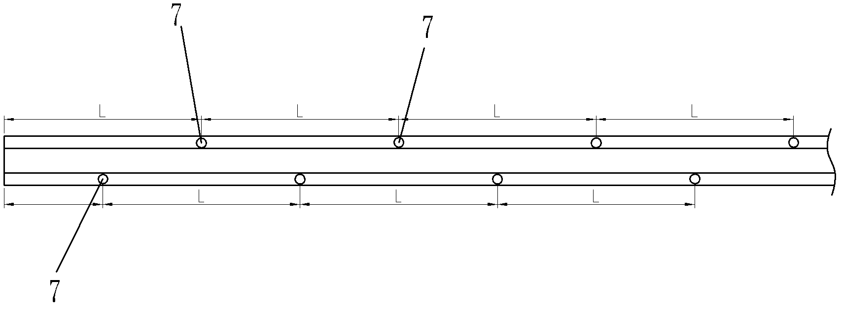
[0027] Such as figure 1 The casting crane trolley track shown in , includes a steel rail 1, which is laid on the rail bearing plate 2, and a stopper 4 is welded on both sides of the lower part of the rail 3, and the stopper 4 is welded on the rail bearing plate 2 at the same time. Wherein a space 5 is formed among the block 4, the rail 1 and the rail bearing plate 2, and an adhesive 6 is injected into the space 5 so that the rail 1 and the rail bearing plate 2 are bonded and fixed together. The lower part of the rail 3 is provided with a through hole 7 along the direction perpendicular to the axis of the rail, and the through hole 7 communicates with the space 5

[0028] When the track is connected by multiple sections of rails 1, the adjacent rails 1 are fixed together by welding. The purpose is to eliminate the gap between the join...


PUM


Abstract

The invention discloses a trolley track of a ladle crane. The trolley track comprises at least one section of steel rail which is paved on a rail bearing plate. The trolley track is characterized in that two stop blocks are respectively welded on two sides at the lower part of the steel rail and are simultaneously welded on the rail bearing plate; space is formed among the stop blocks, the steel rail and the rail bearing plate; a binding agent is injected and molded in the space; the steel rail and the rail bearing plate are fixedly bound together by the binding agent; and a through hole is formed in the lower part of the steel rail along the direction perpendicular to the axis of the steel rail and is communicated with the space. The trolley track disclosed by the invention cannot generate displacement under the action of thrust, the mounting precision is kept and favorable moving environment of the trolley is ensured, and thus the service life of trolley wheels and the service life of electrical equipment are prolonged and safety accidents caused by the loosening of a rail pressing device are avoided. Meanwhile, the frequencies of maintaining and repairing can be reduced and the service cost is reduced.

Description

technical field [0001] The invention specifically relates to a track on which a crane trolley travels and an installation method thereof, in particular to a trolley track capable of preventing displacement and an installation method thereof. Background technique [0002] The crane’s cart braking, trolley running and braking will produce a certain vertical and horizontal thrust on the trolley track, while the working level of the casting crane is generally not lower than A7, and the working level of the trolley is generally not lower than M6. The working level of trolley lifting is generally not lower than M8, and the working level of large trucks is generally not lower than M7, so the thrust is relatively large. [0003] The cast crane trolley track in the prior art includes steel rails, and the rails are usually fixed with a pressure plate, that is, a rubber plate or a steel plate is placed between the steel rail and the rail bearing plate, and then fixed with a pressure pl...

Claims


Application Information

Patent Timeline
Patent Type & Authority Applications(China)
IPC IPC(8): B66C7/08
Inventor 仇步新崔慧莲陈锁张艳丽
Owner ELEPHANT KING HEAVY IND
Why Eureka
Try Eureka