
Speed regulation asynchronous magnetic coupler with adjustable radial air gap

A magnetic coupling and radial air gap technology, applied in electrical components, electromechanical devices, electromechanical transmission devices, etc., can solve the problems of limited application scope, high requirements on magnetic isolation cover materials, and difficult installation, and achieve overload protection. The effect of good performance and starting performance, expanding the application range and improving the utilization rate

Active Publication Date: 2014-02-12
JIANGSU UNIV
View PDF3 Cites 1 Cited by
  • Summary
  • Abstract
  • Description
  • Claims
  • Application Information

AI Technical Summary

Problems solved by technology

[0002] In the field of mechanical engineering transmission technology, couplings are frequently used components in the power transmission process of mechanical systems. In traditional mechanical transmission systems, rigid mechanical methods are usually used to connect the driving shaft and driven shaft in different mechanisms. , to transmit torque and movement; however, the transmission system through mechanical connection is prone to failure; in addition, due to the mechanical connection, the centering accuracy between devices is very high, which is for large equipment or high-precision transmission systems Alignment installation is very difficult. Once there is an error in the alignment, the transmission system may be twisted during the work process, resulting in a major accident; and in some heavy-duty starting occasions, when the load is too large, the equipment is blocked or stuck When the phenomenon occurs, if the motor protector fails, it will also cause the motor to be burned during the working process. Therefore, it is urgent to seek a device that has no wear and vibration, can transmit constant torque and different torque, and improve transmission efficiency.
[0003] As a form of magnetic transmission, magnetic couplings, compared with traditional mechanical couplings, have no mechanical contact, friction and wear during the transmission process, and have overload protection functions. The biggest feature of magnetic couplings is that Completely seal the inner rotor and the driven shaft, change the dynamic seal into a static seal, completely solve the problem of "running, popping, dripping, and leaking" in mechanical transmission pumps, and eliminate flammable, flammable and Explosive, toxic, and harmful media leak through the pump seal, effectively ensuring safe production; however, the magnetic coupling is limited in its application range due to the demagnetization of the permanent magnet on the rotor at high temperature. , in the occasions that need to output constant torque and different torque, how to replace the frequency conversion speed regulation of the motor, realize the stepless speed change of the transmission, and improve the efficiency transmission of the coupling is one of the key issues to expand the application range of the magnetic coupling. Based on The above characteristics make it necessary to study the transmission structure of magnetic couplings.
[0004] In the patent CN201110024791.8, a permanent magnet coupling governor is disclosed, including: a cylindrical conductor rotor, a cylindrical magnetic isolation cover, a cylindrical permanent magnet rotor, and a regulator. Under the action of the regulator, the cylindrical The axial movement of the magnetic isolation cover changes the size of the facing area of ​​the cylindrical conductor rotor and the cylindrical permanent magnet rotor, thereby changing the size of the output torque. The speed regulation principle of this coupling is simple, but the magnetic isolation cover In addition, the application occasions of this coupling are limited and cannot be used in occasions with high sealing requirements and high temperature; in the patent CN201110219054.3, an adjustable axial asynchronous magnetic coupling is disclosed Device, including: inner rotor assembly, outer rotor assembly, speed regulating device and spacer sleeve, through the speed regulating device, the movement between the driving and driven wheels of the friction wheel is changed, so that the meshing area between the permanent magnet and the copper bar is changed , so as to realize the torque output. This kind of coupling is easy to operate when adjusting the speed, but it is difficult to accurately determine the adjustment distance, and the utilization rate of the permanent magnet is low; the coupling of the present invention is an adjustable radial air gap. The high-speed asynchronous magnetic coupling uses the radial movement of the movable card body evenly distributed on the disc body to realize the radial movement in or out of the permanent magnet, and accurately adjust the radial air gap length between the permanent magnet and the guide bar , changing the force of the air-gap magnetic field to achieve different speed and torque outputs, thereby achieving the purpose of stepless speed change, and at the same time improving the utilization rate of permanent magnets, providing some new ideas for the development of magnetic transmission

Method used


Image

  • Speed regulation asynchronous magnetic coupler with adjustable radial air gap
  • Speed regulation asynchronous magnetic coupler with adjustable radial air gap
  • Speed regulation asynchronous magnetic coupler with adjustable radial air gap

Examples


Embodiment 1

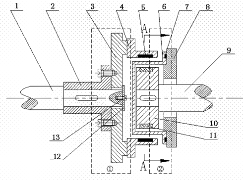
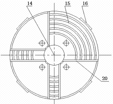
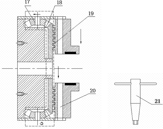
[0032] The working principle of embodiment 1: when the outer rotor rotates with the motor, the permanent magnet 5 embedded in the bottom groove of the movable card body 4 will generate an alternating magnetic field in the air gap whose size and direction change according to a certain law, according to According to Lenz's law, when the guide bar 11 cuts the magnetic force line, an induced current will be generated. This current interacts with the alternating magnetic field, so that the inner rotor receives an electromagnetic torque in the same direction as the alternating magnetic field, so that the inner rotor rotates. When the wrench 21 rotates any one of the four small bevel gears 17 on the circumference clockwise, the large bevel gear 18 in the disc body 14 rotates counterclockwise, and the plane thread 15 on the back side also rotates counterclockwise, thereby driving the movable card body 4 move radially toward the center at the same time, the length of the air gap between...

Embodiment 2

[0033] The working principle of embodiment 2: on the basis of embodiment 1, the guide bar 11 in the inner rotor assembly is replaced with the copper skin 23 wrapped on the inner solid rotor, when the wrench 21 turns clockwise the four Any one of the small bevel gears 17, the large bevel gear 18 in the disc body 14 rotates counterclockwise, and the plane thread 15 on its back side also rotates counterclockwise, driving the movable card body 4 to move radially toward the center of the disc body 14 at the same time. , the length of the air gap between the permanent magnet 5 and the outer copper skin 23 becomes smaller, the force of the air gap magnetic field becomes larger, and the output torque becomes larger; During any one, the large bevel gear 18 rotates clockwise, and the plane thread 15 on its back side also rotates clockwise, driving the movable card body 4 away from the center of the disc body 14 at the same time, the air gap length between the permanent magnet 5 and the o...


PUM


Abstract

The invention relates to the technical field of mechanical engineering transmission, and in particular relates to a speed regulation asynchronous magnetic coupler with an adjustable radial air gap. In the speed regulation asynchronous magnetic coupler, the radial movement of active card bodies which are uniformly distributed on a disc body is utilized to realize radial shift-in or shift-out of a permanent magnet, accurately adjust the gas gap length between the permanent magnet and a conducting bar, change the acting force of an air-gap field and realize the outputs of different rotation speeds and torques, thereby realizing purpose of stepless speed change. The speed regulation asynchronous magnetic coupler provided by the invention is mainly used between a motor and a load in industries such as oil refining, chemical industry, coal and electricity generation, or used in power transmission devices of other related mechanisms.

Description

technical field [0001] The invention relates to the technical field of mechanical engineering transmission, in particular to a speed-regulating asynchronous magnetic coupling with adjustable radial air gap, which is mainly used for the connection between motors and loads in oil refining, chemical industry, coal, power generation and other industries or other related mechanisms in the power transmission unit. Background technique [0002] In the field of mechanical engineering transmission technology, couplings are frequently used components in the power transmission process of mechanical systems. In traditional mechanical transmission systems, rigid mechanical methods are usually used to connect the driving shaft and driven shaft in different mechanisms. , to transmit torque and movement; however, the transmission system through mechanical connection is prone to failure; in addition, due to the mechanical connection, the centering accuracy between devices is very high, which...

Claims


Application Information

Patent Timeline
Patent Type & Authority Patents(China)
IPC IPC(8): H02K51/00
Inventor 杨超君周曰华孔令营蒋毅一
Owner JIANGSU UNIV
Learn More