
Backlight module

A technology of backlight modules and backplanes, applied in optics, light sources, electric light sources, etc., can solve problems such as electrical connectors falling off, large light strips hitting parts, and easy failures

Inactive Publication Date: 2012-08-01
AU OPTRONICS (SUZHOU) CORP LTD +1
View PDF4 Cites 4 Cited by
  • Summary
  • Abstract
  • Description
  • Claims
  • Application Information

AI Technical Summary

Problems solved by technology

[0004] However, in the conventional backlight modules using light-emitting diodes (Light-Emitting Diode, LED) as the light source, the light bar of the light-emitting diode (light bar) must first be connected and fixed to the electrical connector and the wire by welding, and then connected to the The control board (control board) is turned on, and manpower is required to assemble it through screws during the period, which is very time-consuming, laborious and prone to failure
Moreover, there may also be a large number of light bar collisions on the production line, causing electrical connectors to fall off
In addition, screw assembly will also cause liquid crystal unevenness (Mura) phenomenon that cannot be solved by LCD monitors

Method used


Image

  • Backlight module
  • Backlight module
  • Backlight module

Examples


Embodiment Construction

[0068] A number of embodiments of the present invention will be disclosed in the following figures. For the sake of clarity, many practical details will be described together in the following description. It should be understood, however, that these practical details should not be used to limit the invention. That is, in some embodiments of the present invention, these practical details are unnecessary. In addition, for the sake of simplifying the drawings, some commonly used structures and components will be shown in a simple and schematic manner in the drawings.

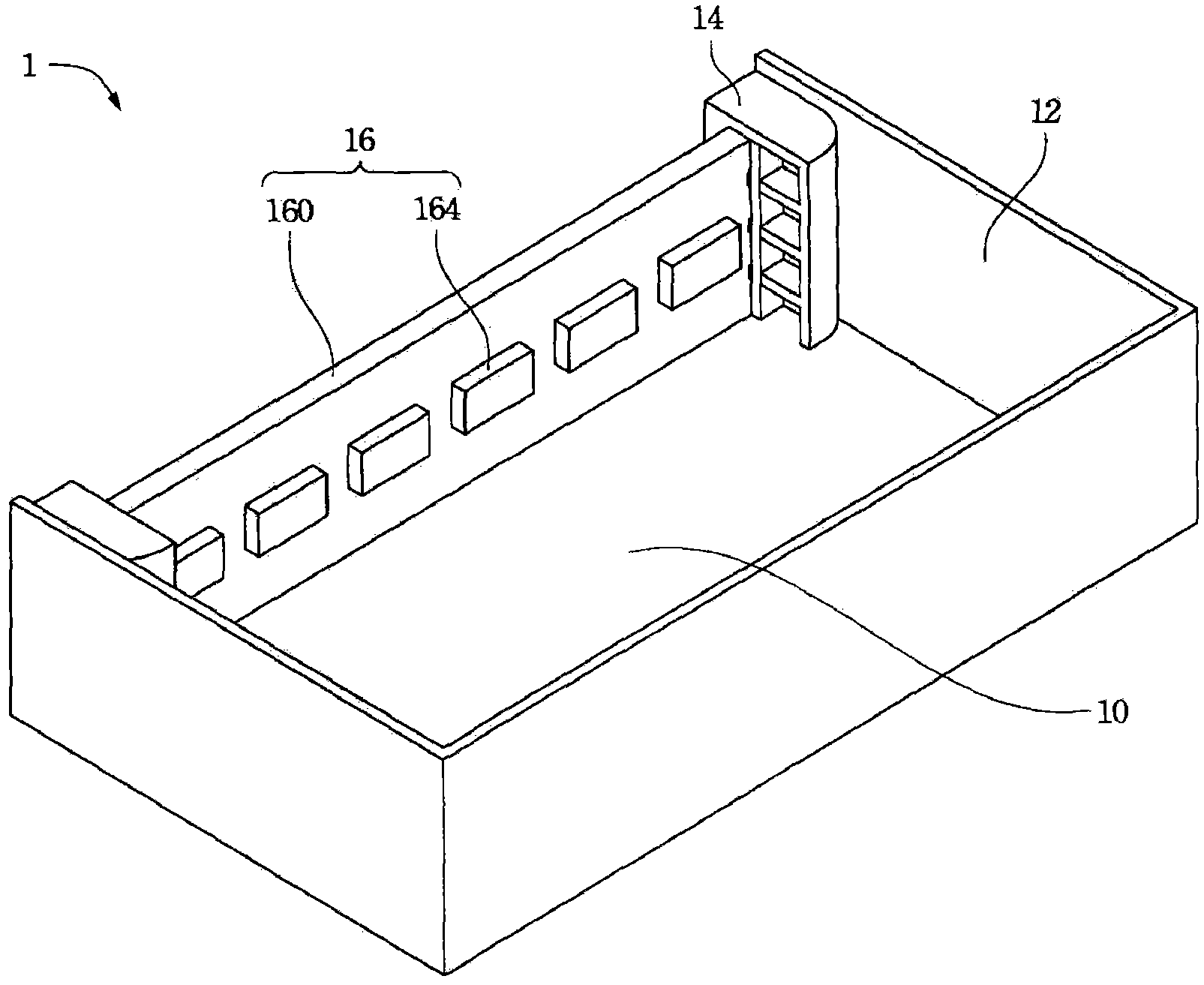
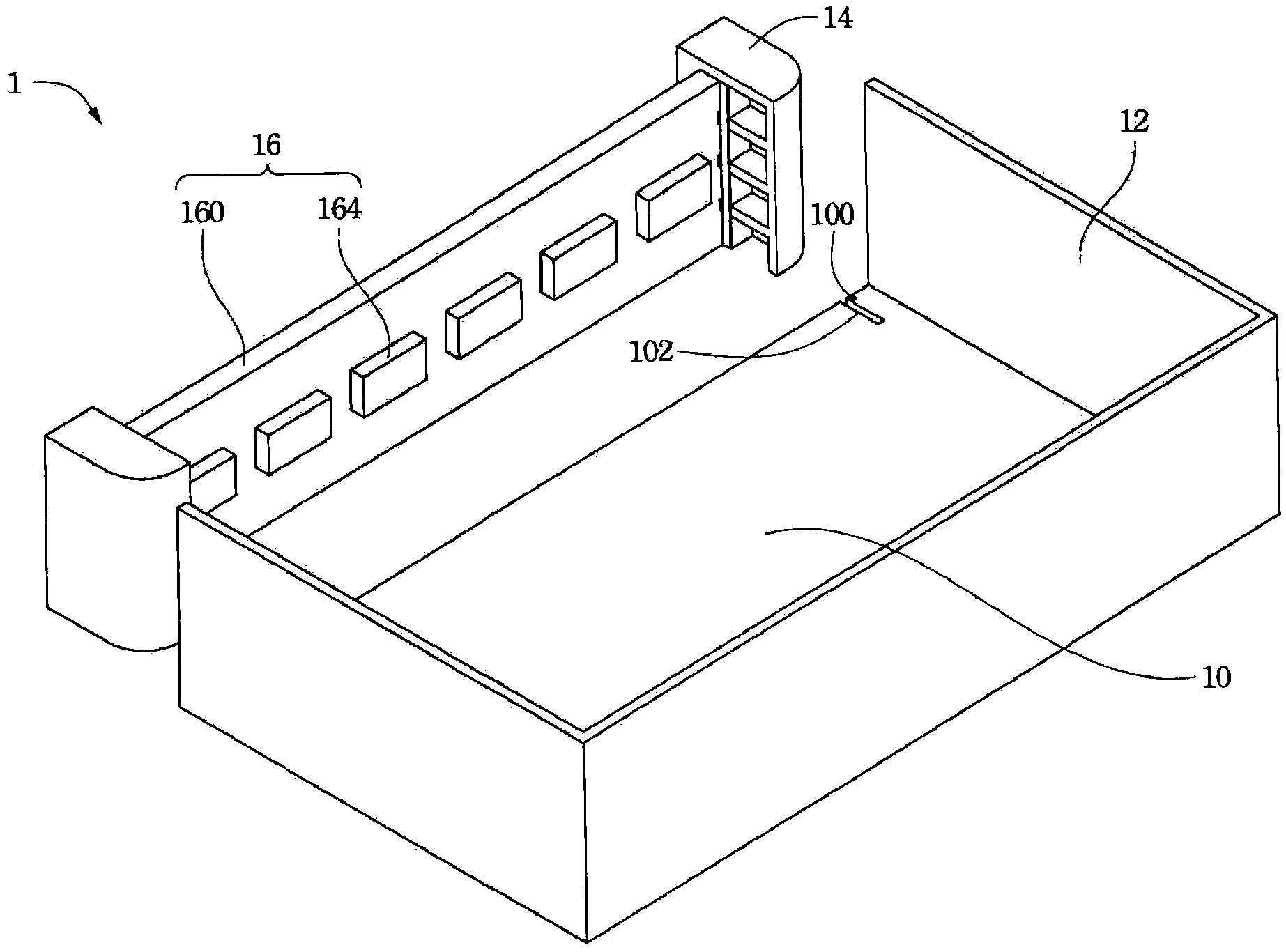
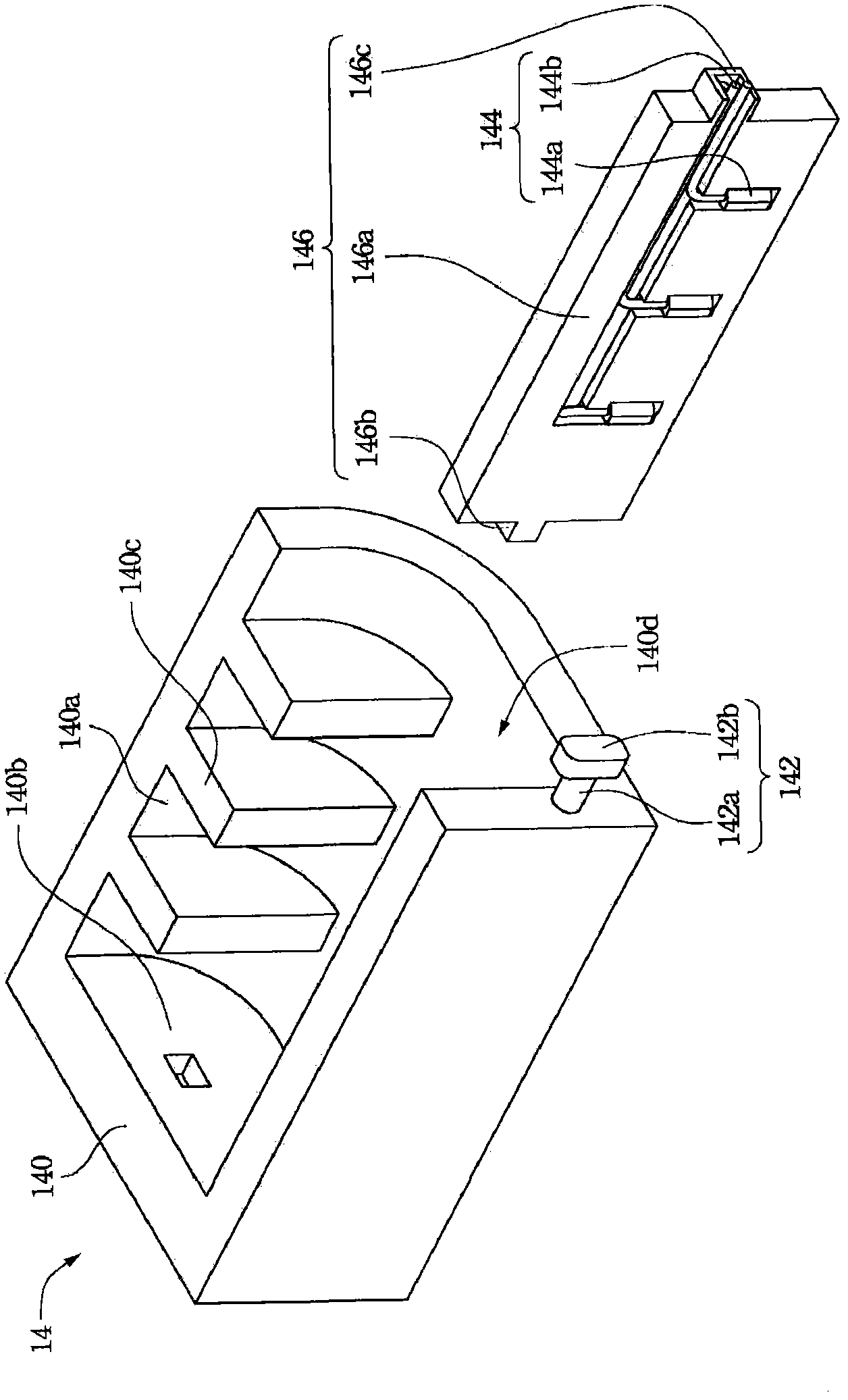
[0069]In one embodiment of the present invention, a backlight module is provided. More specifically, it mainly changes the power supply mode of the traditional backlight module. The backlight module of the present invention adopts a new electrical connector, which can simultaneously supply power to the light bar and perform the functions of locking and positioning, eliminating the need to assemble the backlight m...


PUM


Abstract

The invention provides a backlight module, which comprises a back plate, a side plate, an electrical connector and a light bar. A clamping groove is inwards formed at the edge of the back plate, and the side plate is connected with the edge of the back plate. The electrical connector comprises a body, a clamping piece and a conductive piece. The body is arranged on the back plate and propped against the side plate. The body is provided with an accommodating groove. The accommodating groove is back to the side plate. The clamping piece is connected with the body, penetrates through the back plate and is used for clamping the clamping groove so as to prevent the electrical connector from leaving the back plate. The conductive piece is arranged in the accommodating groove, penetrates through the back plate and is electrically connected with an external power supply. The light bar is arranged on the back plate and comprises a substrate. The tail end of the substrate is accommodated in the accommodating groove and clamped between the body and the back plate. By adopting the backlight module, the electrical connector has the functions of electrifying, clamping and positioning the light bar, so that related manufacturing procedure for assembling the backlight module by using screws is eliminated; and the electrical connector is not required to be artificially welded. Moreover, a non-uniform liquid crystal phenomenon caused by locking the screws can be eliminated, and the yield of a product is greatly promoted.

Description

technical field [0001] The invention relates to a liquid crystal display device, in particular to a backlight module in the liquid crystal display device. Background technique [0002] In recent years, due to the rapid development of electronics and information industries, the related products have become increasingly sophisticated. As far as the current personal computer field is concerned, in addition to seeking higher-speed, more computing-capable computing units and a variety of interface devices to meet user needs, the industry is also developing thin, light and small portable computers. focus areas. Taking liquid crystal display as an example, it has the advantages of high image quality, small size, light weight, low voltage drive, low power consumption and wide application range, so it is widely used in portable TVs, mobile phones, video recorders, etc. , notebook computers, desktop monitors and other consumer electronics products have become the mainstream of displ...

Claims


Application Information

Patent Timeline
Patent Type & Authority Applications(China)
IPC IPC(8): F21S8/00F21V17/10F21V23/00G02F1/13357F21Y101/02
Inventor 童雨舟
Owner AU OPTRONICS (SUZHOU) CORP LTD
Learn More