
Button structure and assembly method thereof

An assembly method and key technology, which are applied to emergency protection devices, emergency actuators, electrical components, etc., can solve the problems that the two sliding rods are easy to fall off, the production efficiency cannot be improved, the connecting rod and the positioning groove are not conducive to automatic mechanical installation, etc. Reduce manual installation errors and labor costs, improve production efficiency, and save labor assembly effects

Active Publication Date: 2019-05-03
DARFON ELECTRONICS (SUZHOU) CO LTD +1
View PDF5 Cites 0 Cited by
  • Summary
  • Abstract
  • Description
  • Claims
  • Application Information

AI Technical Summary

Problems solved by technology

In order to ensure that the two sliders do not break away from the positioning groove, the tolerance gap between the two sliders and the positioning groove is required to be relatively high. If the tolerance gap is too small, the sliding of the two sliders will not be smooth. If the tolerance gap is too large, the two sliders will Rod comes off easily
In addition, the current design of connecting rods and positioning slots is not conducive to automatic mechanical installation, so it cannot improve production efficiency

Method used


Image

  • Button structure and assembly method thereof
  • Button structure and assembly method thereof
  • Button structure and assembly method thereof

Examples


Embodiment Construction

[0077] The following descriptions of the various embodiments refer to the accompanying drawings to illustrate specific embodiments in which the present invention can be practiced. The directional terms mentioned in the present invention, such as "upper", "lower", "front", "rear", "left", "right", "side", etc., are only referring to the directions of the attached drawings. Therefore, the directional terms used are used to illustrate and understand the present invention, but not to limit the present invention.

[0078] In the following embodiments, the same parts are denoted by the same symbols in different drawings.

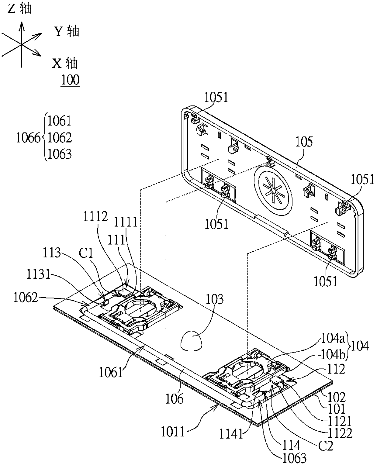
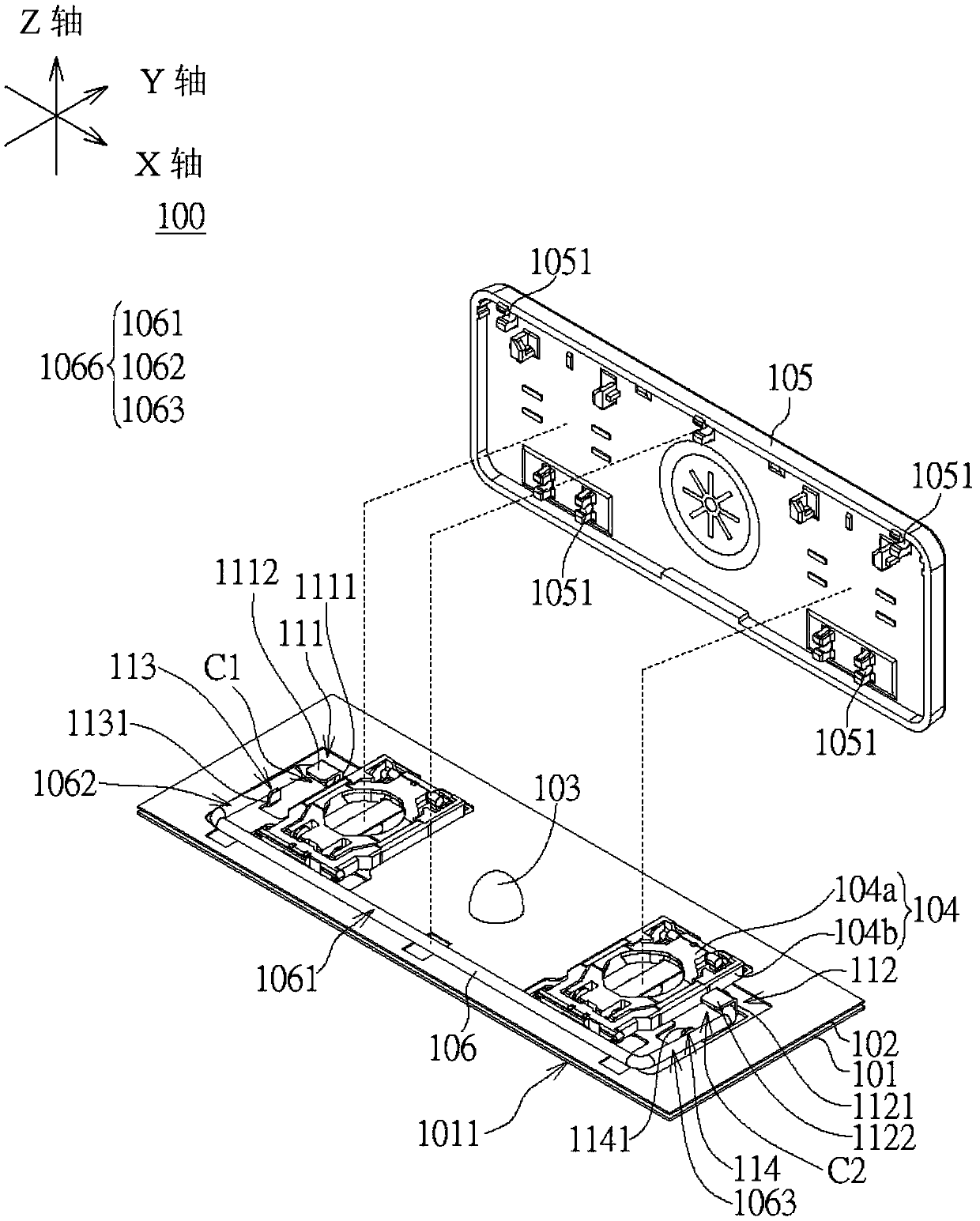
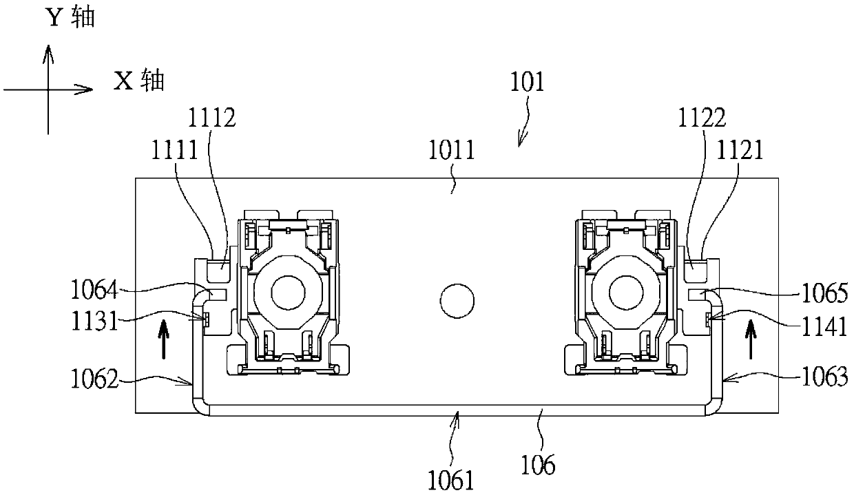
[0079] Please refer to Figure 1A , Figure 1B , Figure 2A and Figure 2B , the key structure 100 according to the first embodiment of the present invention includes a bottom plate 101 , a circuit layer 102 , an elastic body 103 , a supporting structure 104 , a keycap 105 and a connecting rod 106 . The base plate 101 has a base plate body 1011 and a first pos...


PUM


Abstract

The present invention discloses a button structure and an assembling method thereof. The button structure comprises a base plate, a key cap and a connection rod. The first location portion of the base plate is provided with a first Z-axis arm and a first Y-axis arm. The second location portion of the base plate is provided with a second Z-axis arm and a second Y-axis arm. The third location portion of the base plate is provided with a third Z-axis arm. The fourth location portion of the base plate is provided with a fourth Z-axis arm. The connection rod is provided with a central rod, a first Y-axis rod, a second Y-axis rod, a first X-axis rod and a second X-axis rod. When the key cap is moved between a pressing position and a releasing position, the first Y-axis rod is moved along the Y-axis direction in a first storage space, the first Y-axis arm restricts the movement range of the first X-axis rod on the Z axis, the second X-axis rod is moved along the Y-axis direction in a second storage space, and the second Y-axis arm restricts the movement range of the second X-axis rod on the Z axis. The button structure and the assembling method thereof are convenient to assemble and high in precision so as to improve the production efficiency and save manpower assembling.

Description

technical field [0001] The present invention relates to a button structure and its assembly method, and in particular to a button structure and its assembly method for automatic mechanical installation. Background technique [0002] In the current key structure, in order to make the key move up and down smoothly, a connecting rod is provided between the bottom of the key cap and the bottom plate. The connecting rod is, for example, U-shaped, and a pair of positioning slots are provided on the bottom plate for the two sliding rods of the connecting rod to be inserted and slide up and down inside. In order to ensure that the two sliders do not break away from the positioning groove, the tolerance gap between the two sliders and the positioning groove is required to be relatively high. If the tolerance gap is too small, the sliding of the two sliders will not be smooth. If the tolerance gap is too large, the two sliders will The rod comes off easily. In addition, the current ...

Claims


Application Information

Patent Timeline
Patent Type & Authority Patents(China)
IPC IPC(8): G06F3/02
CPCH01H13/705H01H13/88H01H2221/016H01H2229/064
Inventor 黄达雄王庆余
Owner DARFON ELECTRONICS (SUZHOU) CO LTD
Learn More