
Water storage bottle cap for engine cooling system

A technology for engine cooling and water storage bottles, which is applied in the direction of engine cooling, engine components, machines/engines, etc. It can solve the problems of complex structure of bottle caps, difficult processing, and discomfort of the whole vehicle, and achieves control accuracy that is easy to guarantee, The effect of reducing the difficulty of production and reducing the manufacturing cost

Active Publication Date: 2016-02-03
CHONGQING CHANGAN AUTOMOBILE CO LTD
View PDF6 Cites 0 Cited by
  • Summary
  • Abstract
  • Description
  • Claims
  • Application Information

AI Technical Summary

Problems solved by technology

[0004] 1. Exhaust and suction are set up separately. Due to the influence of the volume of the cap of the water storage bottle, the volume of the valve body is relatively small, which leads to high requirements for the control accuracy of the valve body, and the pressure control is unstable, so that the valve cannot be accurately and timely controlled. the pressure in the bottle;
[0005] 2. Due to the small volume of the valve body, the internal structure of the bottle cap is complicated and difficult to process;
[0006] 3. Due to the small size of the valve body, when there is a vacuum or excessive pressure inside the system, the internal pressure of the system cannot be balanced through the valve body in time, making the whole vehicle in an "uncomfortable" state for a long time, which will shorten the "life" of the whole vehicle

Method used


Image

  • Water storage bottle cap for engine cooling system
  • Water storage bottle cap for engine cooling system
  • Water storage bottle cap for engine cooling system

Examples


Embodiment Construction

[0027] The present invention will be further described below in conjunction with accompanying drawing:

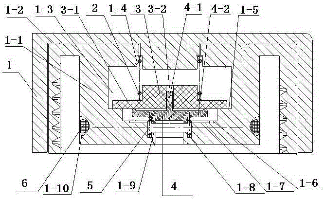
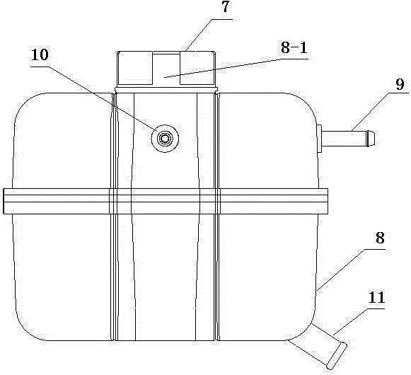
[0028] Such as figure 1 with figure 2 The water storage bottle cap of the engine cooling system shown mainly includes an outer cover 1, a bottle stopper 1-1, an exhaust valve spring 2, an exhaust valve 3, an intake valve 4 and an intake valve spring 5, and the outer cover 1 It is integral with the bottle stopper 1-1, and the outer cover 1 is threadedly connected with the outer wall of the bottle mouth 8-1, and the cover plug 1-1 is closely attached to the inner wall of the bottle mouth 8-1. An annular groove 1-10 is formed on the outer surface, and the sealing ring 6 is set in the annular groove 1-10. The center of the cap plug 1-1 has a stepped hole 1-3 that communicates with the bottle body 8 downwards. The stepped hole 1-3 consists of a first step 1-5, a second step 1-6 and a third step from top to bottom. 1-9 are divided into three stages in turn, the inner diamete...


PUM


Abstract

The invention discloses a water storage bottle cap of an engine cooling system. The water storage bottle cap comprises an outer cap and a cap plug, wherein a stepped hole downwardly communicated with a bottle body is formed in the centre of the cap plug; an exhaust valve spring, an exhaust valve, an air inlet valve and an air inlet valve spring are installed in the stepped hole from top to bottom in sequence; at least one first ventilation hole is formed in the outer cap; the stepped hole is communicated with outside through the first ventilation hole; the stepped hole has at least three stages; the stepped hole has first, second and third steps from top to bottom in sequence; the upper end of the exhaust valve spring is in contact with the inner side of the top surface of the outer cap; the lower end of the exhaust valve spring is supported on the exhaust valve; the exhaust valve is matched with the first step under the elastic action of the exhaust valve spring; the upper end of the air inlet valve spring is in contact fit with the air inlet valve; the lower end of the air inlet valve spring is supported on the third step; the air inlet valve is in contact fit with the second step under the elastic action of the air inlet valve spring; and a second ventilation hole is formed in the exhaust valve. The water storage bottle cap disclosed by the invention has the advantages of simple structure, easy manufacture and low cost; furthermore, the control precision is easy to ensure.

Description

technical field [0001] The invention belongs to the field of automobile engine cooling systems, and in particular relates to a water storage bottle cap of the engine cooling system. Background technique [0002] The automotive engine cooling system includes radiators, electric fans, thermostats, temperature sensors, water storage bottles and other components. Operate under pressure conditions. During the working process of the engine, the temperature of the coolant in the system will rise and expand, causing the coolant flowing through the cylinder liner to evaporate, and the steam generated will cool the system, especially when the radiator is under a relatively high pressure. A good pressure relief will cause damage to the radiator; when the engine stops working, the temperature of the coolant in the cooling system will drop, the volume will decrease, and the pressure in the system will be lower than atmospheric pressure. For this reason, it is necessary to set up a wate...

Claims


Application Information

Patent Timeline
Patent Type & Authority Patents(China)
IPC IPC(8): F01P11/00
Inventor 梁易超蔡操平孟锐郭文洋钱小军
Owner CHONGQING CHANGAN AUTOMOBILE CO LTD
Learn More