Method and device for braking revolution of upper car of rotary drilling rig

A technology for rotary drilling rigs and rotary braking, which is applied to rotary drilling rigs, drilling equipment and methods, and rotary drilling, and can solve problems such as large instantaneous kinetic energy, easy damage, and easy-to-break reducers, and achieve increased Slewing braking ability, easy to use, and the effect of reducing damage

Active Publication Date: 2012-08-01
SUNWARD INTELLIGENT EQUIP CO LTD
View PDF8 Cites 0 Cited by
  • Summary
  • Abstract
  • Description
  • Claims
  • Application Information

AI Technical Summary

Problems solved by technology

In this process, due to the sudden braking of the reducer, the instantaneous kinetic energy is very large, and the instantaneous impact load acting on the output shaft of the reducer is very large, which is easy to damage the reducer.
In addition, during the drilling process, due to the drill bit touching the hard rock or the inaccurate positioning of the hole position after unloading the soil each time, the drilling is biased, the drill bit is subjected to a large eccentric load, and a strong torque is transmitted to the reducer, resulting in damage to the reducer
At present, the impact torque during rotation and operation is borne by the output shaft of the reducer, so it is easy to be damaged. After adding an independent brake, the output shaft of the brake can share this torque and improve the reliability of the equipment.

Method used


Image

  • Method and device for braking revolution of upper car of rotary drilling rig
  • Method and device for braking revolution of upper car of rotary drilling rig
  • Method and device for braking revolution of upper car of rotary drilling rig

Examples


Embodiment Construction

[0022] The present invention will be further described in combination with the accompanying drawings and specific embodiments.

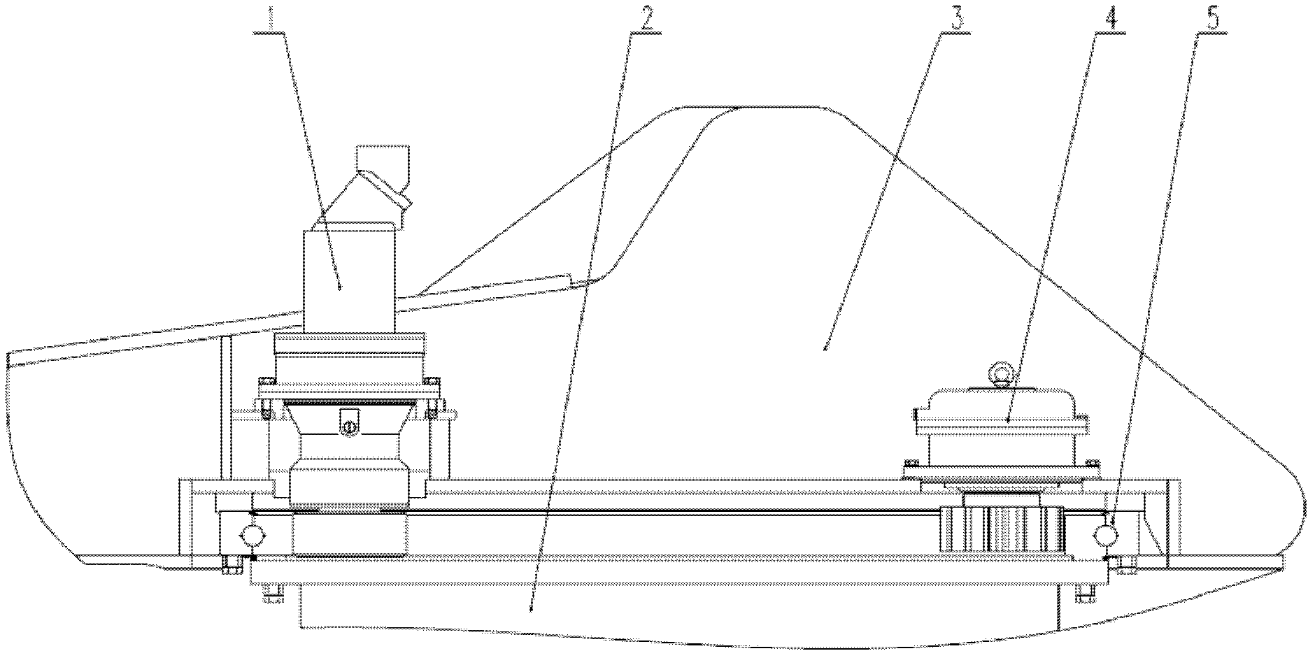
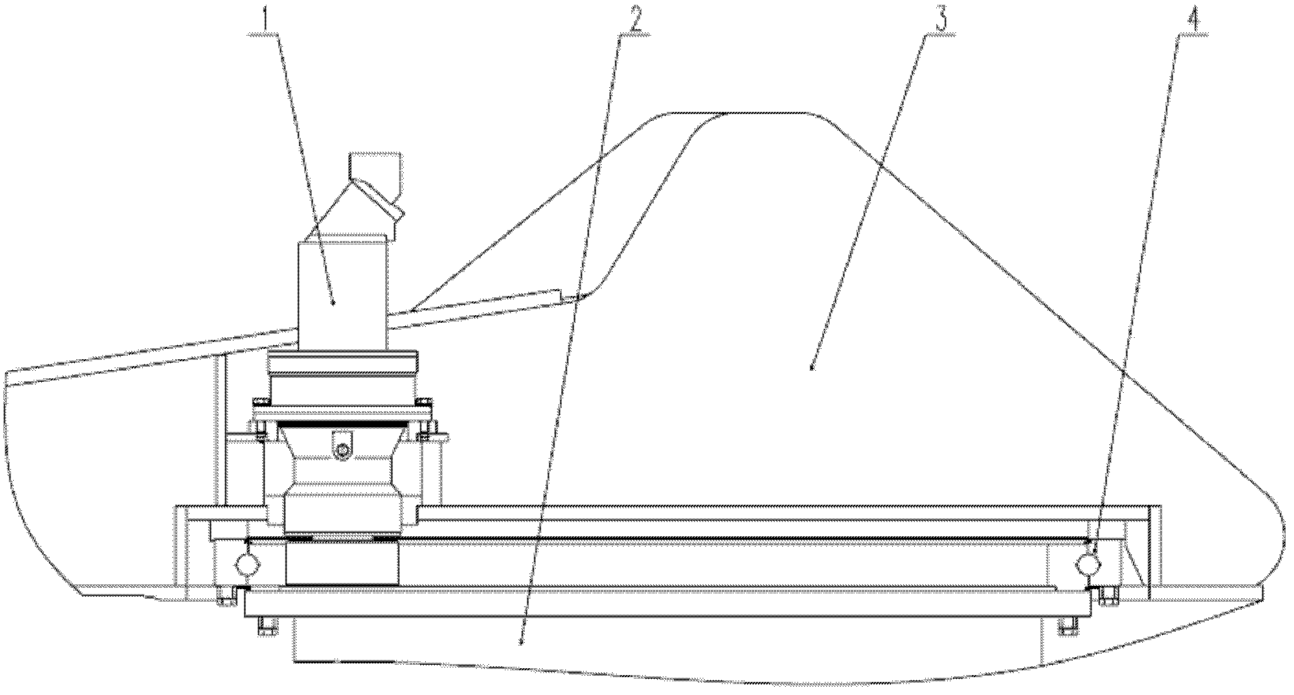
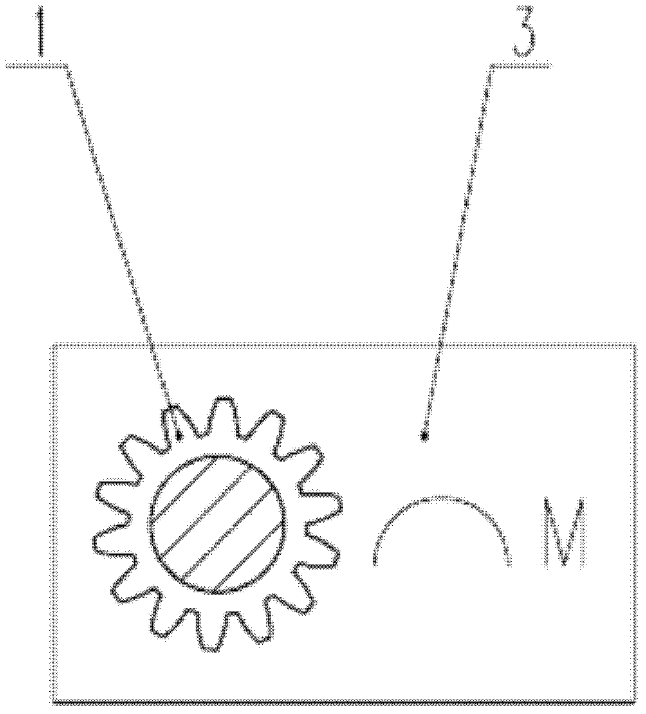
[0023] see figure 1 , the upper car 3 and the lower car 2 are connected through the slewing support 5 to ensure that the drilling machine can work at 360°. The slewing reducer 1 is installed on the upper car 3, and the output shaft of the slewing reducer 1 is engaged with the slewing support 5 for transmission. Normally closed hydraulic pressure The cylinder block of the brake 4 is installed on the upper car 3, the gear shaft of the normally closed hydraulic brake 4 is meshed with the slewing support 5 for transmission, and the slewing reducer 1 and the normally closed hydraulic brake 4 share a pilot oil circuit for oil supply through the drilling rig to ensure The reducer and the brake are turned on and off at the same time.

[0024] The normally closed hydraulic brake 4 is in a self-locking and opening state to meet the braking requirements of the...


PUM


Abstract

The invention discloses a method and a device for braking revolution of an upper car of a rotary drilling rig. The device comprises an upper car (3), a lower car (2), a rotary support (5), a rotary speed reducer (1) and a hydraulic brake (4), wherein at least one set of hydraulic brake is arranged on the upper car (3); a cylinder body of the hydraulic brake is arranged on the upper car (3); a gear shaft of the hydraulic brake is meshed with the rotary support (5) to drive; and a control oil route of the hydraulic brake and the control oil route of the rotary speed reducer (1) share one route of guide oil route to supply oil. The device is low in required cost and simple in use. The revolution braking ability of the drilling rig and the braking ability during drilling operation are effectively improved, and the damage to the rotary speed reducer is reduced to the greatest extent.

Description

technical field [0001] The invention relates to a braking method, in particular to a rotary braking method for boarding a rotary drilling rig, and also relates to a device for realizing the braking method. Background technique [0002] At present, the rotary drilling rigs in the market basically use telescopic drill pipes to operate. The drilling process is to drill a bucket full of soil, lift the drill to the ground, turn around 90° to unload the soil, turn back to the original hole position to drill, and repeat the above. action. In this process, due to the sudden braking of the reducer, the instantaneous kinetic energy is very large, and the instantaneous impact load acting on the output shaft of the reducer is very large, which is easy to damage the reducer. In addition, during the drilling process, because the drill bit encounters hard rock or the location of the positioning hole is inaccurate after unloading each time, the drill bit is biased, and the drill bit is sub...

Claims


Application Information

Patent Timeline
IPC IPC(8): E21B3/02F16D65/22F16D121/12
Inventor 朱建新凡知秀吴新荣熊明强
Owner SUNWARD INTELLIGENT EQUIP CO LTD
Why Eureka
Try Eureka