
Grinding mechanism for abrasive belt grinding machine

An abrasive belt grinder and grinding technology, which is applied in the field of machine tools, can solve problems such as the inconstant bearing force of the abrasive belt mechanism, the complexity of the belt deviation adjustment and lateral vibration devices, and the uncontrollable tension of the abrasive belt, etc., to achieve The effect of light weight, simple structure and small shape

Inactive Publication Date: 2012-08-01
DONGFANG TURBINE CO LTD
View PDF6 Cites 15 Cited by
  • Summary
  • Abstract
  • Description
  • Claims
  • Application Information

AI Technical Summary

Problems solved by technology

The common abrasive belt grinding mechanism has the following weaknesses: 1. The tension force of the abrasive belt cannot be controlled, especially when the thickness of the surface machining allowance of the part is inconsistent, the bearing force of the abrasive belt mechanism is not constant
2. The abrasive belt deflection adjustment and lateral vibration device are complicated, which is not conducive to the integration of the abrasive belt grinding device

Method used


Image

  • Grinding mechanism for abrasive belt grinding machine
  • Grinding mechanism for abrasive belt grinding machine
  • Grinding mechanism for abrasive belt grinding machine

Examples


Embodiment Construction

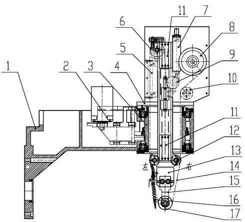
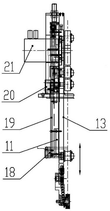
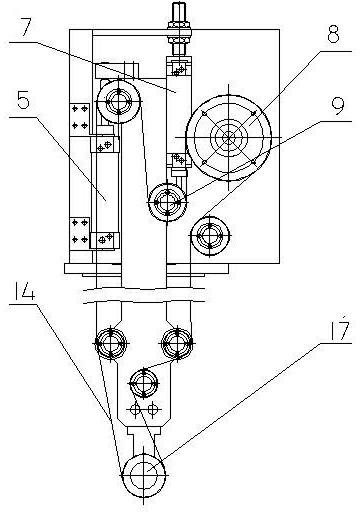
[0019] Such as Figure 1~5 As shown: the present invention is a grinding mechanism of an abrasive belt grinder, which is connected to the rotating spindle of the machine tool through a support arm 1 . Grinding mechanism is provided with driving wheel 8 and its driving device, driven wheel and contact wheel 17, abrasive belt 14 is sleeved on driving wheel 8, driven wheel and contact wheel 17, and the bottom of contact wheel 17 forms abrasive belt grinding head. The grinding mechanism includes a fixed machine base 19 and a displacement device 13, the fixed machine base 19 is connected with the end of the support arm 1, and the fixed machine base 19 is provided with a moving guide rail 11 along the vertical direction, and the displacement device 13 corresponds to the movement guide rail 11 and the fixed machine. Seat 19 movably cooperates, slides up and down. The contact wheel 17 is arranged at the bottom of the displacement device 13, that is, the abrasive belt grinding head is...


PUM


Abstract

The invention provides a grinding mechanism for an abrasive belt grinding machine. A supporting arm is connected with a rotating main shaft of a machine tool; a driving wheel, a driving device of the driving wheel, a driven wheel and a contact wheel are arranged on the grinding mechanism; an abrasive belt is sleeved on the driving wheel, the driven wheel and the contact wheel; and an abrasive belt grinding head is formed at the bottom of the contact wheel. The grinding mechanism comprises a fixed base and a displacement device, wherein the fixed base is connected with the supporting arm; a movement guide rail is arranged on the fixed base along the vertical direction; the displacement device is matched with the fixed base in a movable mode corresponding to the movement guide rail and slides up and down; the contact wheel is arranged at the bottom of the displacement device; a displacement driver and a displacement controller are arranged on the displacement device; and the abrasive belt grinding head is contacted with a surface to be machined in a free floating mode under the gravity action of the displacement device and the coordination action of the displacement driver and the displacement controller. The grinding mechanism can be conveniently and quickly operated, and constant-force grinding is realized; and the grinding mechanism is automatically operated in a full numerical control mode, so that the working efficiency is improved, the cost is saved, and large-scale popularization, usage and production are facilitated.

Description

technical field [0001] The invention is mainly applied to machine tools, in particular to a grinding mechanism on a sand belt grinding or polishing machine tool for blades of steam turbines, gas turbines and the like. Background technique [0002] The steam turbine blade is a complex thin-walled part with a free-form surface in space, and the curvature changes greatly. It is prone to deformation after CNC milling, resulting in uneven distribution of grinding allowance. It is difficult to guarantee the accuracy of blades by manual polishing, and the production site environment is harsh. Due to the mature technology of CNC milling machine tools, the milling head cover is detachable, and a grinding device is designed and invented that can be displaced on the CNC milling machine tool to reduce the machine tool investment of the production plant. The known abrasive belt grinding mechanism mainly consists of three parts: 1, the abrasive belt tensioning mechanism. Commonly used i...

Claims


Application Information

Patent Timeline
IPC IPC(8): B24B21/16B24B21/20B24B21/18
Inventor 袁秀坤李德平余继斌
Owner DONGFANG TURBINE CO LTD
Learn More