
Two-degree-of-plane-freedom redundant drive parallel mechanism and machine tool with same

A degree of freedom, plane technology, used in milling machines, milling machine equipment, metal processing machinery parts, etc., can solve the problems of reduced mechanical efficiency, increased restraint reaction force of kinematic pairs, increased driving force, etc., to improve dynamic performance, stress Uniform, stiffness-increasing effect

Active Publication Date: 2012-08-01
TSINGHUA UNIV
View PDF8 Cites 22 Cited by
  • Summary
  • Abstract
  • Description
  • Claims
  • Application Information

AI Technical Summary

Problems solved by technology

However, this type of structure puts forward high requirements on the manufacturing and installation accuracy of each connecting rod, because the manufacturing and installation errors will cause the components and the kinematic pair to be forced to deform during the movement, which will significantly increase the driving force, and at the same time, the constraints of the kinematic pair will be reversed. The force increases sharply, which leads to accelerated wear, reduced mechanical efficiency, causes large vibration, impact and noise of the system, and reduces the reliability, precision and life of the mechanism

Method used


Image

  • Two-degree-of-plane-freedom redundant drive parallel mechanism and machine tool with same
  • Two-degree-of-plane-freedom redundant drive parallel mechanism and machine tool with same
  • Two-degree-of-plane-freedom redundant drive parallel mechanism and machine tool with same

Examples


Embodiment Construction

[0015] The present invention will be described in detail below in conjunction with the accompanying drawings and embodiments.

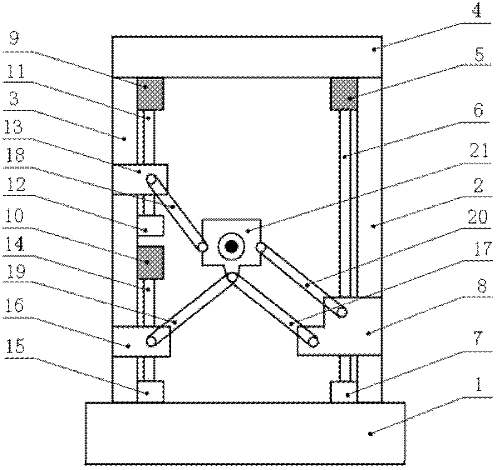
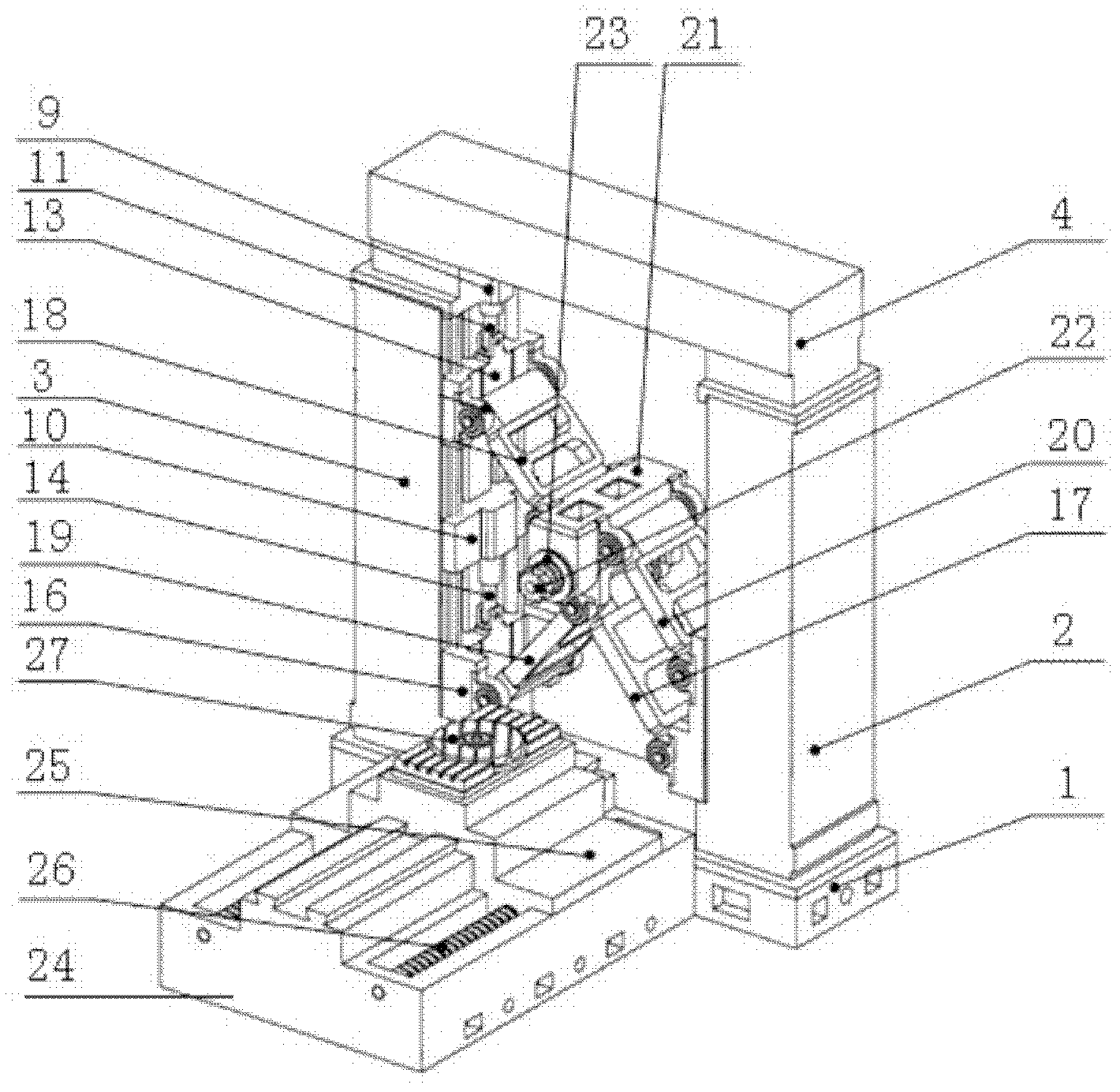
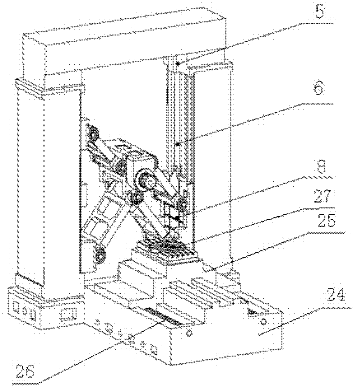
[0016] Such as figure 1 As shown, the present invention includes a base 1 on which a first column 2 and a second column 3 are vertically spaced apart, and the tops of the first column 2 and the second column 3 are connected to the same beam 4 . Sliding guide rails are provided on opposite sides of the first column 2 and the second column 3 . The upper part of the first column 2 is provided with a first servo motor 5, the output end of the first servo motor 5 is connected to the first ball screw 6, and the lower end of the first ball screw 6 is vertically supported on the first screw support seat 7, The first screw support seat 7 is arranged on the first column 2 , and the first ball screw 6 is provided with a first slider 8 which can vertically move up and down along the guide rail on the first column 2 . The top of the second column 3 is provided w...


PUM


Abstract

The invention relates to a two-degree-of-plane-freedom redundant drive parallel mechanism and a machine tool with the same. The two-degree-of-plane-freedom redundant drive parallel mechanism is characterized by comprising a base, two vertical columns with a slide guide are vertically disposed on the base, and the upper ends of the two vertical columns are connected together through a beam. A servo motor, a slider, a ball screw and a screw support are disposed on one vertical column, and a first connecting bar and a fourth connecting bar disposed on the slider are equal to each other in lengthand form a parallelogram mechanism. Two servo motors, two sliders, two ball screws and two screw supports are disposed on the other vertical column, and a second connecting bar and a third connectingbar are disposed on the two sliders respectively. The first connecting bar, the second connecting bar, the third connecting bar and the fourth connecting bar are all connected with a same moving platform. The second connecting bar is disposed above the moving platform, and hinge ends of the second connecting bar and the fourth connecting bar with the moving platform are at same height. The first connecting bar and the third connecting bar are disposed below the moving platform, and hinge points of the first connecting bar and the third connecting bar with the moving platform are at the same position. By using the two-degree-of-plane-freedom redundant drive parallel mechanism, singularity of an operating space can be lessened, and force transmission performance and dynamic performance are improved.

Description

technical field [0001] The invention relates to a parallel mechanism and a machine tool using the mechanism, in particular to a plane two-degree-of-freedom redundant drive parallel mechanism and a machine tool using the mechanism. Background technique [0002] As a new type of machine tool that has appeared in the past two decades, parallel machine tool is the product of the combination of parallel robot technology and modern machine tool technology. It has the characteristics of high rigidity, good dynamic performance, high degree of modularization, easy reconfiguration and simple mechanical structure. In line with the development trend of high-speed, flexible and integrated manufacturing, it has aroused widespread concern in the industry. The earliest Stewart platform is a typical 6-DOF parallel mechanism. This type of parallel mechanism has been used in the design of machine tools. The first parallel machine tool designed and manufactured based on the Stewart platform was...

Claims


Application Information

Patent Timeline
Patent Type & Authority Applications(China)
IPC IPC(8): B23Q1/46B23C1/027
Inventor 吴军李铁民姜峣唐晓强
Owner TSINGHUA UNIV
Learn More