Elastic boring bar

A boring bar and elastic technology, applied in the direction of boring bars, can solve the problems of reducing the overall rigidity of boring bars, large size and shape errors, restrictions, etc., to improve precision and efficiency, reduce the driving force of tie rods, and reduce the axis effect on length

Active Publication Date: 2014-05-07
HUAZHONG UNIV OF SCI & TECH
View PDF6 Cites 0 Cited by
  • Summary
  • Abstract
  • Description
  • Claims
  • Application Information

AI Technical Summary

Problems solved by technology

However, many years of engineering applications and experiments have shown that: 1) once a large disturbance occurs in the cutting force during processing, it will bring large size and shape errors, so its rigidity needs to be further improved; 2) because the invention only One-way compensation (one-way radial micro-feed) can be realized, which limits the application range of this technology; 3) Since the rigidity of the elastic boring bar and the maximum compensation range are mutually restricted, for example, if the rigidity is required, the maximum compensation range is small , and vice versa, which also limits the application range of the boring bar; 4) The screw of the ejector bar assembly is assembled inside the deformable body, which limits the design space of the push rod, thereby reducing the strength and rigidity of the push rod; 5) the The connecting sleeve of the invented boring bar increases the axial length of the boring bar and adds a link between the elastic boring bar and the main shaft, thereby reducing the overall rigidity of the boring bar. In addition, the contact point between the connecting sleeve and the tie rod It is easy to wear and has a significant adverse effect on the accuracy and reliability of compensation, and needs to be replaced regularly

Method used


Image

  • Elastic boring bar
  • Elastic boring bar
  • Elastic boring bar

Examples


Embodiment Construction

[0038] In order to make the object, technical solution and advantages of the present invention clearer, the present invention will be further described in detail below in conjunction with the accompanying drawings and embodiments. It should be understood that the specific embodiments described here are only used to explain the present invention, not to limit the present invention.

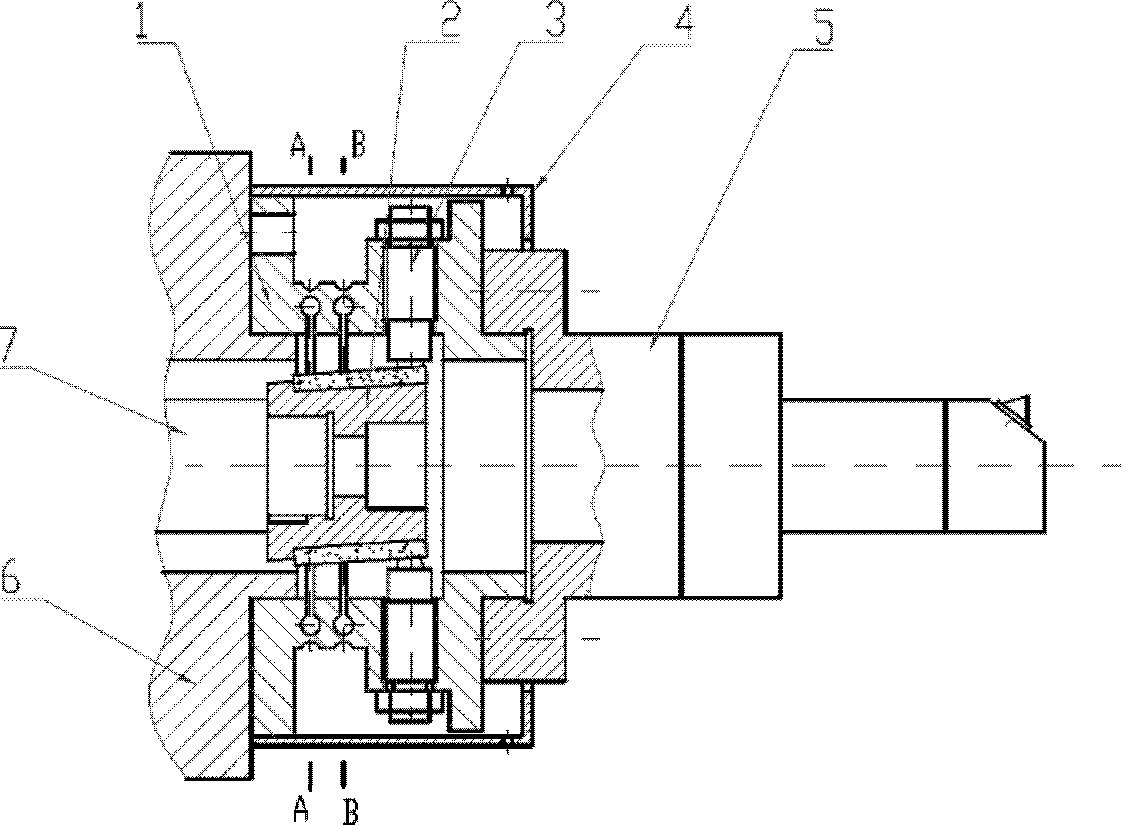
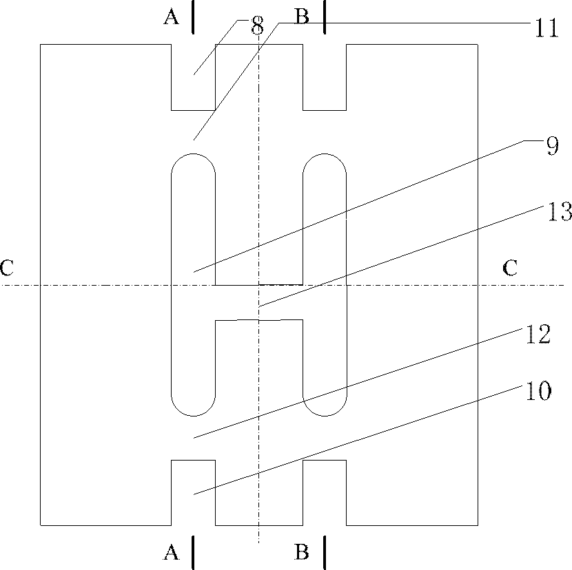
[0039] see figure 1 , figure 1 is a schematic cross-sectional view of the overall structure of the elastic boring bar according to the present invention. Such as figure 1 As shown in , the elastic boring bar according to the present invention is composed of elastic deformation body 1, inclined block 2, ejector rod assembly 3, cutter bar assembly 5, pull rod 7 and optional protective cover 4 and other components. The elastic deformation body 1 as the main body constituting the elastic boring bar can be, for example, a cylindrical structure and made of materials such as spring steel. The front en...


PUM


Abstract

The invention discloses an elastic boring bar capable of realizing radial automatic adjustment of a boring cutter. The elastic boring bar comprises an elastic deforming body, an inclined block, a jacking rod component and a pulling rod, wherein the elastic deforming body is served as a boring bar main body; the inclined block is arranged in the elastic deforming body; four elastic wall structures functioned as hinges are formed on the middle part in the elastic deforming body; the inclined block is arranged in the front end of the elastic deforming body and is provided with upper and lower two inclined planes which are parallel to each other; the pulling rod is connected with the inclined block and is used for driving the inclined block to axially move together; and the jacking rod component is used for generating radial shifting when the inclined block is driven by the pulling rod to axially move together. The elastic boring bar according to the invention is capable of increasing the whole rigidity of the boring bar, realizing the bidirectional complementation of radial adjustment and correspondingly increasing the accuracy and reliability of the radial adjustment of the boring cutter.

Description

technical field [0001] The invention belongs to the field of machining tool accessories, and more specifically relates to an elastic boring bar capable of realizing automatic radial adjustment of a boring tool during the boring process. Background technique [0002] In mass production and manufacturing, high-precision boring is an important finishing method for holes and turning circles. However, due to the inevitable tool wear and other random factors, the machining accuracy will inevitably decrease, so the adjustment of the tool is inevitable; therefore, the boring processing technology with the function of automatic and precise micro-adjustment of the tool has become a guarantee and improvement of processing quality and efficiency. In addition, the interpolation machining of special-shaped holes also requires the tool to achieve a small amount of radial feed during the machining process. [0003] At present, the devices for realizing micro radial feed in boring mainly in...

Claims


Application Information

Patent Timeline
Patent Type & Authority Patents(China)
IPC IPC(8): B23B29/02
Inventor 邵新宇邓建春
Owner HUAZHONG UNIV OF SCI & TECH
Why Eureka
Try Eureka